Instruction Manual
D102748X012
DLC3010 Digital Level Controller
Field Communicator Menu Tree
May 2018
106
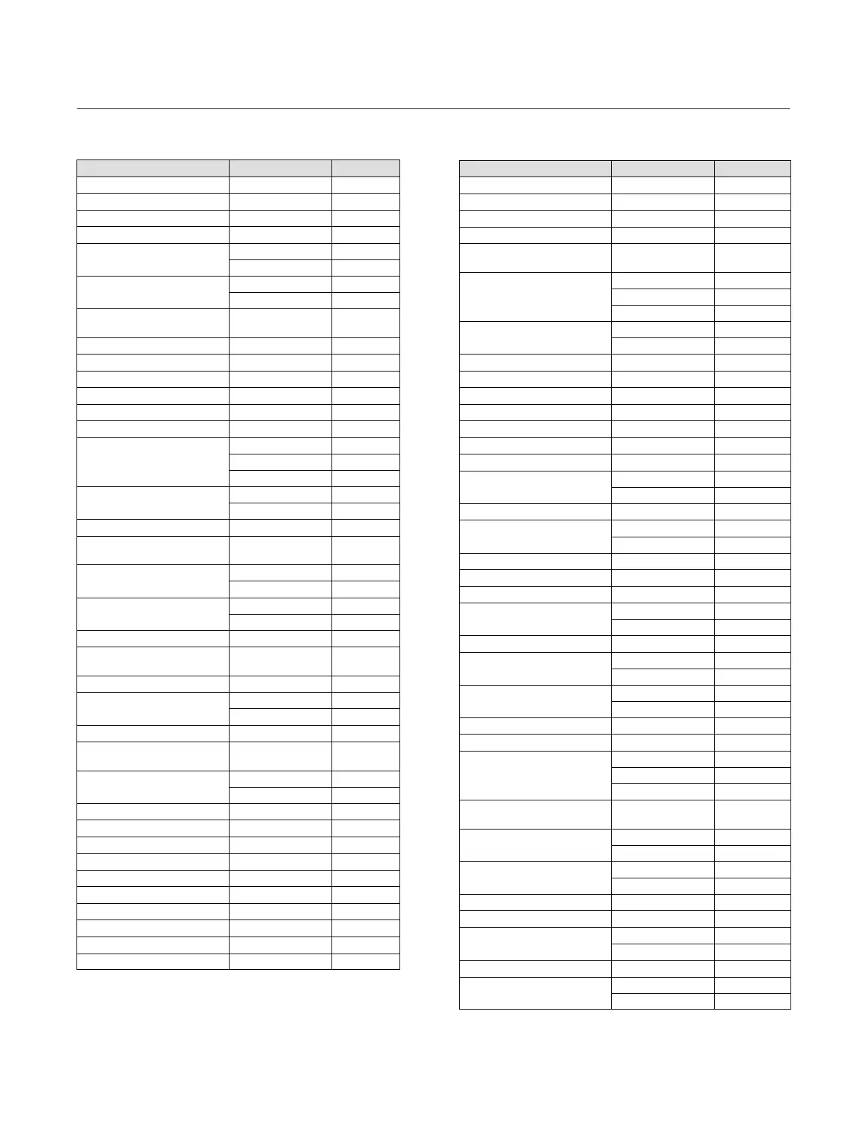
Table
B‐1.
Fast
Key
Sequence
Function Fast-Key Sequence See Figure
% Range, Mapped Variables 3-2-1-1-5 B‐7
% Range, Variables 3-2-6 B‐7
Alarm Jumper 1-7-3-1-1 B‐2
Analog Output 1-7 B‐2
Analog Output Action
1-6-3-6 B‐2
2-2-3-6 B‐4
Analog Output Calibration
1-6-2-2 B‐2
2-4-2-2 B‐6
Analog Output, Mapped
Variables
3-2-1-1-4 B‐7
Analog Output, Variables 3-2-5 B‐7
Apparent SG
(1)
3-2-1-3-2-4 B‐7
Buffer NVM 3-2-1-4-3-3 B‐7
Buoyant Force 3-2-1-3-2-3 B‐7
Burst Mode 2-2-6-2 B‐4
Burst Option 2-2-6-3 B‐4
Capture Zero
1-6-1-3-1 B‐2
2-4-1-3-1 B‐6
3-4-2-2-1 B‐7
Change Action
1-6-3-7 B‐2
2-2-3-7 B‐4
Change Material, Torque Tube 2-2-1-3-2 B‐4
Change Mode, Instrument
Display
(2)
2-2-7-3 B‐4
Change Protection
Hot Key-3 B‐1
1-7-3-2-2 B‐2
Change PV
2-2-2-2 B‐4
Hot Key-5 B‐1
Change Torque Rate 2-2-1-3-5 B‐4
Compenated Torque Rate,
Compensation
3-2-1-2-1 B‐7
Configuration NVM 3-2-1-4-3-1 B‐7
Date
1-7-1-5 B‐2
2-2-5-5 B‐4
DD Information 1-7-2-5 B‐2
Decimal Places, Instrument
Display
(2)
2-2-7-4 B‐4
Description
1-7-1-6 B‐2
2-2-5-6 B‐4
Device ID 1-7-1-4-1 B‐2
Device, Revision 1-7-2-2 B‐2
Device Status 1-1 B‐2
Displacer Length
(3)
2-2-1-2-1 B‐4
Displacer Length, Constants 3-2-1-3-1-8 B‐7
Displacer Volume 2-2-1-2-2 B‐4
Displacer Volume, Constants 3-2-1-3-1-6 B‐7
Displacer Weight 2-2-1-2-3 B‐4
Displacer Weight, Constants 3-2-1-3-1-4 B‐7
Display Mode
(2)
2-2-7-2 B‐4
Function Fast-Key Sequence See Figure
Distributor 1-7-1-2 B‐2
Driver Rod Length 2-2-1-2-4 B‐4
Driver Rod Length, Constants 3-2-1-3-1-2 B‐7
Dry Deflection, Constants 3-2-1-3-1-5 B‐7
Edit Compensation, Torque
Tube
2-2-1-3-3 B‐4
Enter Contstant SG
Hot Key-8 B‐1
2-2-4-4-3
(5)
B‐4
2-2-4-4-4
(4)
B‐4
Final Assembly Number
1-7-1-4-4 B‐2
2-2-5-4 B‐4
Final PV 3-2-1-3-2-7 B‐7
Firmware, Revision 1-7-2-3 B‐2
Free Time Remaing 3-2-1-4-2-1 B‐7
Guided Calibration 2-4-1-1 B‐6
Hall Drive 3-2-1-4-1-2 B‐7
Hall Sensor Signal 3-2-1-4-1-1 B‐7
Hardware, Revision 1-7-2-4 B‐2
Instrument Serial Number
1-7-1-4-2 B‐2
2-2-5-2 B‐4
Instrument Setup 2-1 B‐3
Interface Level
(4)
1-4 B‐2
3-3-1-1 B‐7
LCD Configuration 2-2-7-1 B‐4
LCD Test 3-4-1-1 B‐7
Length, Sensor Units 1-2-1-1-1 B‐4
Level Offset
(3)
1-6-3-8 B‐2
2-2-3-8 B‐4
Level Offset, Constants
(3)
3-2-1-3-1-9 B‐7
Liquid Density
(1)
1-5
B‐2
3-3-1-1 B‐7
Liquid Level
(5)
1-3 B‐2
3-3-1-1 B‐7
Load Steam Tables
(4)
2-2-4-4-5 B‐4
Loop Test 3-4-1-2 B‐7
Lower Fluid Density
Hot Key-7 B‐1
2-2-4-4-1
(5)
B‐4
2-2-4-4-2
(4)
B‐4
Lower Fluid Density,
Compensation
(3)
3-2-1-2-3 B‐7
Lower Range Value
1-6-3-5 B‐2
2-2-3-5 B‐4
Lower Sensor Limit
1-6-3-2 B‐2
2-2-3-2 B‐4
Measure SG
(5)
2-2-4-4-4 B‐4
Mechanical Gain, Constants 3-2-1-3-1-3 B‐7
Message
1-7-1-7 B‐2
2-2-5-7 B‐4
Messure SG 2-2-4-4-4 B‐4
Min/Max Calibration
1-6-1-2-1 B‐2
2-4-1-2-1 B‐6
1. In Liquid Density Mode only.
2. Absent when LCD is not installed.
3. Absent in Liquid Density Mode.
4. In Interface Level Mode only.
5. In Liquid Level Mode only
 Loading...


