Instruction Manual
D102748X012
DLC3010 Digital Level Controller
Field Communicator Menu Tree
May 2018
107
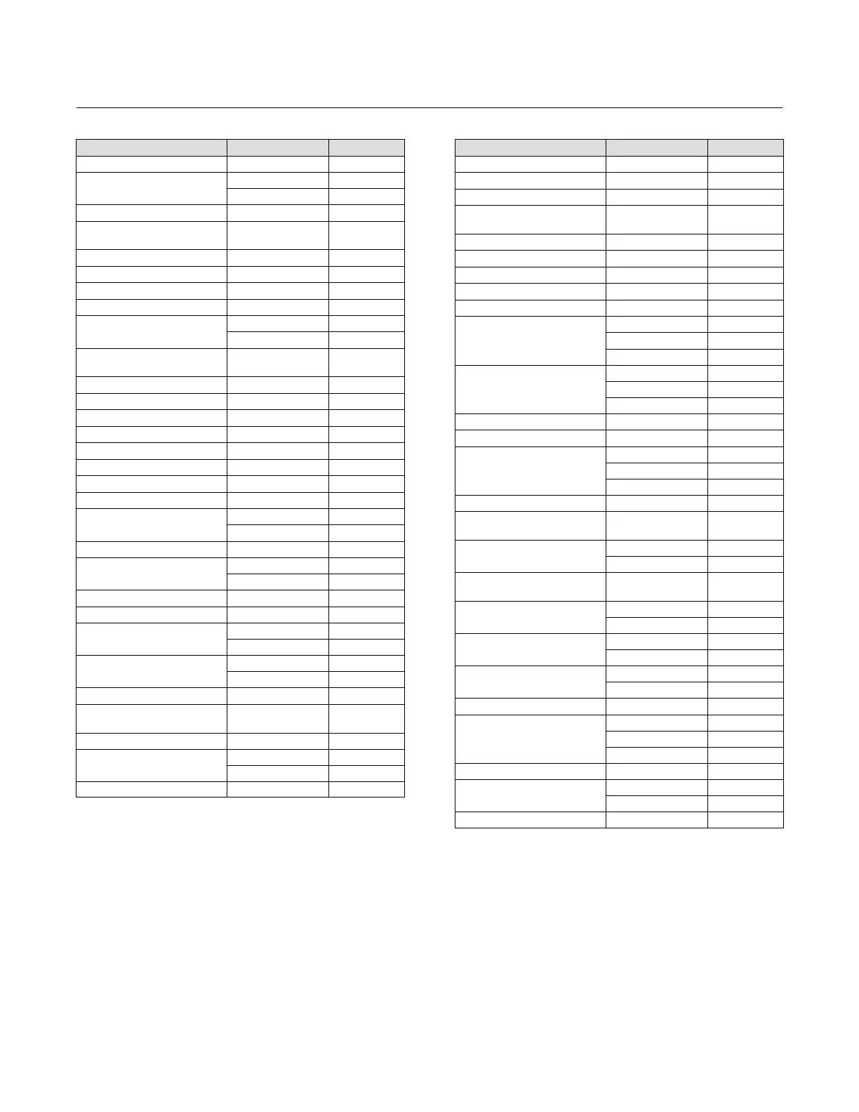
Function Fast-Key Sequence See Figure
Min/Max Calibration 3-4-2-1-2 B‐7
Minimum Span
1-6-3-3 B‐2
2-2-3-3 B‐4
Model 1-7-1-3 B‐2
Overweight Displacer,
Calibration Scenarios
1-6-1-4-2-2 B‐2
Polling Address 2-2-6-1 B‐4
Preliminary PV
(1)
3-2-1-3-2-5 B‐7
Primary Variable 2-2-2-1 B‐4
Primary Variable, Alert Setup 2-3-1 B‐5
Process Temperature
1-6 B‐2
2-2-4-6-1 B‐4
Process Temperature, RTD
Data
(6)
2-2-4-1-1 B‐4
PV Hot Key 4 B‐1
PV, Mapped Variables 3-2-1-1-1 B‐7
Reference Buoyancy
(7)
3-2-1-3-1-7 B‐7
Refresh Jumper 1-7-3-1-3 B‐2
Reset Device 3-4-4-2 B‐7
Restore Factory Defaults 3-4-4-1 B‐7
Rotation Change 3-2-1-3-2-2 B‐7
RTD Wire Resistance
(8)
2-2-4-1-2 B‐4
Scaled D/A Trim, AO
Calibration
1-6-2-2-2 B‐2
2-4-2-2-2 B‐6
Scaled PV
(3)
3-2-1-3-2-6 B‐7
Scan Device
Hot Key-1 B‐1
2-2-6-4 B‐4
Secondary Variable 2-2-2-3 B‐4
Sensor Rotation 3-2-1-3-2-1 B‐7
Sensor Serial Number
1-7-1-4-3 B‐2
2-2-5-3 B‐4
Set Level Offset
(3)
1-6-3-9 B‐2
2-2-3-9 B‐4
Signal Levels 1-7-3-1-3 B‐2
Standard Hardware,
Calibration Scenarios
1-6-1-4-2-1 B‐2
SV, Mapped Variables 3-2-1-1-2 B‐7
Tag
1-7-1-1 B‐2
2-2-5-1 B‐4
Temperature Calibration
1-6-2-1 B‐2
Function Fast-Key Sequence See Figure
Temperature Calibration 2-4-2-1 B‐6
Temperature, Alert Setup 2-3-2 B‐5
Temperature, Sensor Units 2-2-1-1-5 B‐4
Theoretical Calibration,
Calibration Scenarios
1-6-1-4-2-4 B‐2
Third Variable 2-2-2-4 B‐4
Torque Rate 2-2-1-3-4 B‐4
Torque Rate, Sensor Units 2-2-1-1-4 B‐4
Transducer NVM 3-2-1-4-3-2 B‐7
Trends 3-3 B‐7
Trim Gain
1-6-1-3-2 B‐2
2-4-1-3-2 B‐6
3-4-2-2-2 B‐7
Trim Zero
1-6-1-3-3 B‐2
2-4-1-3-3 B‐6
3-4-2-2-3 B‐7
TT Material 2-2-1-3-1 B‐4
TV, Mapped Variables 3-2-1-1-3 B‐7
Two Point Calibration
1-6-1-2-2 B‐2
2-1-4-2-2 B‐6
3-4-2-1-2 B‐7
Universal, Revision 1-7-2-1 B‐2
Unknown Density, Calibration
Scenarios
1-6-1-4-2-3 B‐2
Upper Fluid Density
(4)
Hot Key-7 B‐1
2-2-4-4-1 B‐4
Upper Fluid Density,
Compensation
(4)
3-2-1-2-2 B‐7
Upper Range Value
1-6-3-4 B‐2
2-2-3-4 B‐4
Upper Sensor Limit
1-6-3-1 B‐2
2-2-3-1 B‐4
View/Edit SG Tables
2-2-4-4-2
(5)
B‐4
2-2-4-4-3
(4)
B‐4
Volume, Sensor Units 2-2-1-1-2 B‐4
Weight Calibration
1-6-1-2-3 B‐2
2-4-1-2-3 B‐6
3-4-2-1-3 B‐7
Weight, Sensor Units 2-2-1-1-3 B‐4
Write Protect
Hot Key-2 B‐1
1-7-3-2-1 B‐2
Zero Ref Angle 3-2-1-3-1-1 B‐7
1. In Liquid Density Mode only.
3. Absent in Liquid Density Mode.
4. In Interface Level Mode only.
5. In Liquid Level Mode only
6. When Process Temperature Source is Manual Entry.
7. Absent in Liquid Level Mode.
8. Only if Temperature Source is two-wired RTD.
 Loading...


