DVC6000f Digital Valve Controllers
December 2009
7-16
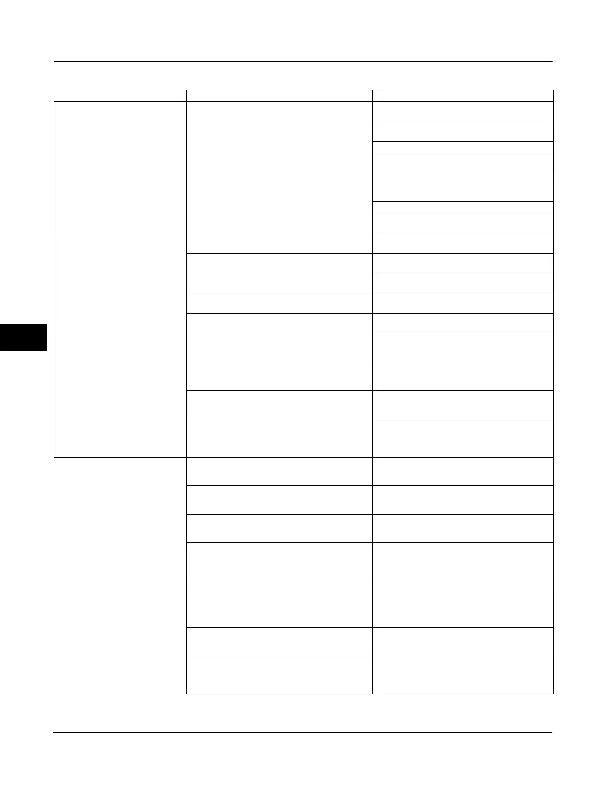
Table 7-2. Instrument Troubleshooting (Continued)
Symptom ActionPossible Cause
2. Device does not stay on segment. 2.a Incorrect signal level.
2.a1 Check that segment is properly terminated (see
host system documentation).
2.a2 Wrong cable type or segment length too long.
See Site Planning Guide.
2.a3 Bad power supply or conditioner.
2.b Excess noise on segment.
2.b1 Check integrity of wiring connections. Make sure
cable shield is grounded only at the control system.
2.b2 Check for corrosion or moisture on terminals in
terminal box (refer to page 7-9 for terminal box
information).
2.b3 Check for bad power supply.
2.c Electronics failing. 2.c. Replace printed wiring board assembly (see
Replacing the PWB Assembly on page 7-7).
3. A value cannot be written to a
parameter.
3.a Resource block parameter Write Lock may be set
to Locked.
3.a Change Write Lock to Not Locked (refer to page
4-4 of Detailed Setup / Blocks).
3.b If a transducer block parameter, the mode may be
incorrect or the parameter may be protected.
3.b1 Check table 4-85. If necessary change the
transducer block target mode to Manual.
3.b2 Check table 4-85. If necessary change data
protection.
3.c You have attempted to write a value that is outside
the valid range.
3.c Check the range values listed for the parameter
(refer to Detailed Setup / Blocks, Section 4).
3.d Function block or in/out block mode may be
incorrect.
3.d. Confirm that block is in correct mode for writing
to any given parameter.
4. Function block actual mode does
not change with target mode.
4.a Resource block actual mode is Out of Service. 4.a Change Resource block target mode to Auto (see
page 4-4, Resource Block Mode, or host system
documentation).
4.b Transducer block actual mode is not Auto. 4.b Change transducer block target mode to Auto
(see page 4-21, Transducer Block Mode or host
system documentation).
4.c Schedules that define when function blocks
execute are not set correctly.
4.c Set the schedules using host system or
configuration tool. All function blocks must be in a
schedule that is downloaded to the device.
4.d Configuration error 4.d Look for configuration error bit in BLOCK_ERR.
By default, all enumerature type parameters are
initialized to 0 (undefined). They must be configured
before the block can be put into service.
5. Input or Output Block does not go
to mode target
5.a Resource block actual mode is Out of Service 5.a Change Resource block target mode to Auto (see
page 4-4, Resource Block Mode, or host system
documentation).
5.b Transducer block actual mode is not Auto. 5.b Change transducer block target mode to Auto
(see page 4-21, Transducer Block Mode or host
system documentation).
5.c Transducer has detected a hardware failure. 5.c A bad status is passed to the block’s READBACK
or FIELD_VAL parameter. See transducer section of
Detailed Setup for repair information.
5.d Wrong output block is active. 5.d Use Outblock Selection to select the desired
output block. The deselected block will have a bad
status for READBACK. This will keep it in IMAN
mode when target is other than OOS.
5.e Output block is not licensed. 5.e The Actual Block Mode (MODE_BLK.ACTUAL
[5.2]) will remain out of service and the block cannot
be scheduled if the block has not bee licensed.
Contact your Emerson Process Management sales
office to upgrade product licensing.
5.f Schedules that define when function blocks
execute are not set correctly.
5.f Set the schedules using host system or
configuration tool. All function blocks must be in a
schedule that is downloaded to the device.
5.g Configuration error. 5.g Look for configuration error bit in BLOCK_ERR.
By default, all enumerature type parameters are
initialized to 0 (undefined). They must be configured
before the block can be put into service.
−Continued−
7

 Loading...


