DVC6000f Digital Valve Controllers
December 2009
2-8
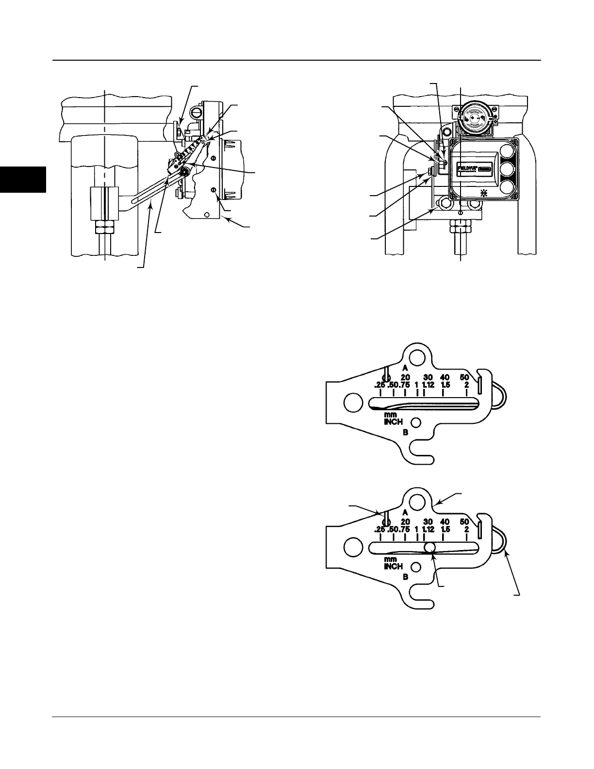
Figure 2-2. FIELDVUE DVC6010f Digital Valve Controller Mounted on Sliding-Stem Actuators with 2 to 4 Inches Travel
CAP SCREW, FLANGED
MACHINE SCREW, FLAT
HEAD
SHIELD
ADJUSTMENT ARM
CONNECTOR ARM
PLAIN WASHER
MACHINE SCREW
MACHINE SCREW,
LOCK WASHER,
HEX NUT
LOCK WASHER
LOCK WASHER
HEX NUT
SPACER
HEX NUT, FLANGED
FEEDBACK ARM
EXTENSION,
BIAS SPRING
4. If valve travel exceeds 2 inches, a feedback arm
extension is attached to the existing 2-inch feedback
arm. Remove the existing bias spring (key 78) from
the 2-inch feedback arm (key 79). Attach the feedback
arm extension to the feedback arm (key 79) as shown
in figure 2-3.
5. Mount the digital valve controller on the actuator as
described in the mounting kit instructions.
6. Set the position of the feedback arm (key 79) on
the digital valve controller to the zero drive position
(zero pressure from Port A with Relay A) by inserting
the alignment pin (key 46) through the hole on the
feedback arm as follows:
For air-to-open actuators (i.e., the actuator
stem retracts into the actuator casing or cylinder as air
pressure to the casing or lower cylinder increases),
insert the alignment pin into the hole marked ‘‘A’’. For
this style actuator, the feedback arm rotates
counterclockwise, from A to B, as air pressure to the
casing or lower cylinder increases.
For air-to-close actuators (i.e., the actuator
stem extends from the actuator casing or cylinder as
air pressure to the casing or upper cylinder increases),
insert the alignment pin into the hole marked ‘‘B’’. For
this style actuator, the feedback arm rotates
clockwise, from B to A, as air pressure to the casing or
upper cylinder increases.
Figure 2-3. Locating Adjustment Arm Pin in Feedback Arm
A7209-1
SPRING RELAXED
SPRING UNDER TENSION OF
ADJUSTMENT ARM PIN
FEEDBACK ARM
ADJUSTMENT
ARM PIN
BIAS
SPRING
BIAS SPRING
2

 Loading...


