Installation
March 2006
2-11
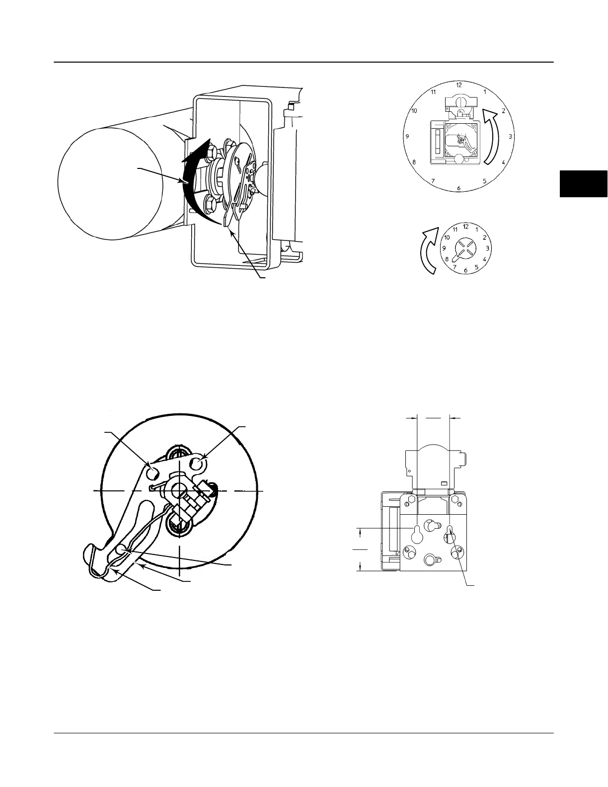
Figure 2-9. Explanation of Travel Indicator Starting Position and Movement if Counterclockwise Orientation is Selected for
“Travel Sensor Motion” in AMS ValveLink
R
Software or the 375 Field Communicator
19B3879-A / DOC-2
STARTING POSITION OF THE TRAVEL INDICATOR
ASSEMBLY IF INCREASING PRESSURE FROM
OUTPUT A DRIVES THE INDICATOR CLOCKWISE
THE POTENTIOMETER SHAFT WILL ROTATE
COUNTERCLOCKWISE AS VIEWED FROM THE
BACK OF THE FIELDVUE INSTRUMENT.
STARTING POSITION OF
TRAVEL INDICATOR ASSEMBLY
(DIGITAL VALVE CONTROLLER
OUTPUT A AT 0 PSI).
MOVEMENT OF TRAVEL
INDICATOR ASSEMBLY WITH
INCREASING PRESSURE FROM
OUTPUT A.
IN THIS POSITION, THE “A” HOLE
IN THE FEEDBACK ARM WILL BE
ALIGNED WITH THE REFERENCE
HOLE IN THE DIGITAL VALVE
CONTROLLERS HOUSING.
DVC6030f FEEDBACK
ARM MOVEMENT
ACTUATOR SHAFT MOVEMENT
E0989
Figure 2-10. Positioning Travel Indicator Pin in the Feedback
Arm (Viewed as if Looking from the Type DVC6030f
toward the Actuator)
FEEDBACK ARM
BIAS SPRING
TRAVEL
INDICATOR PIN
48B4164-B / DOC
HOLE A
HOLE B
Figure 2-11. DVC6005f Series Digital Valve Controller with
Mounting Bracket (Rear View)
10C1796-A / Doc
2 MOUNTING
HOLES
8.6 /.34
57
2.25
72
2.82
2
 Loading...


