FloBoss 103/104 Instruction Manual
1-6 General Information Revised August-2017
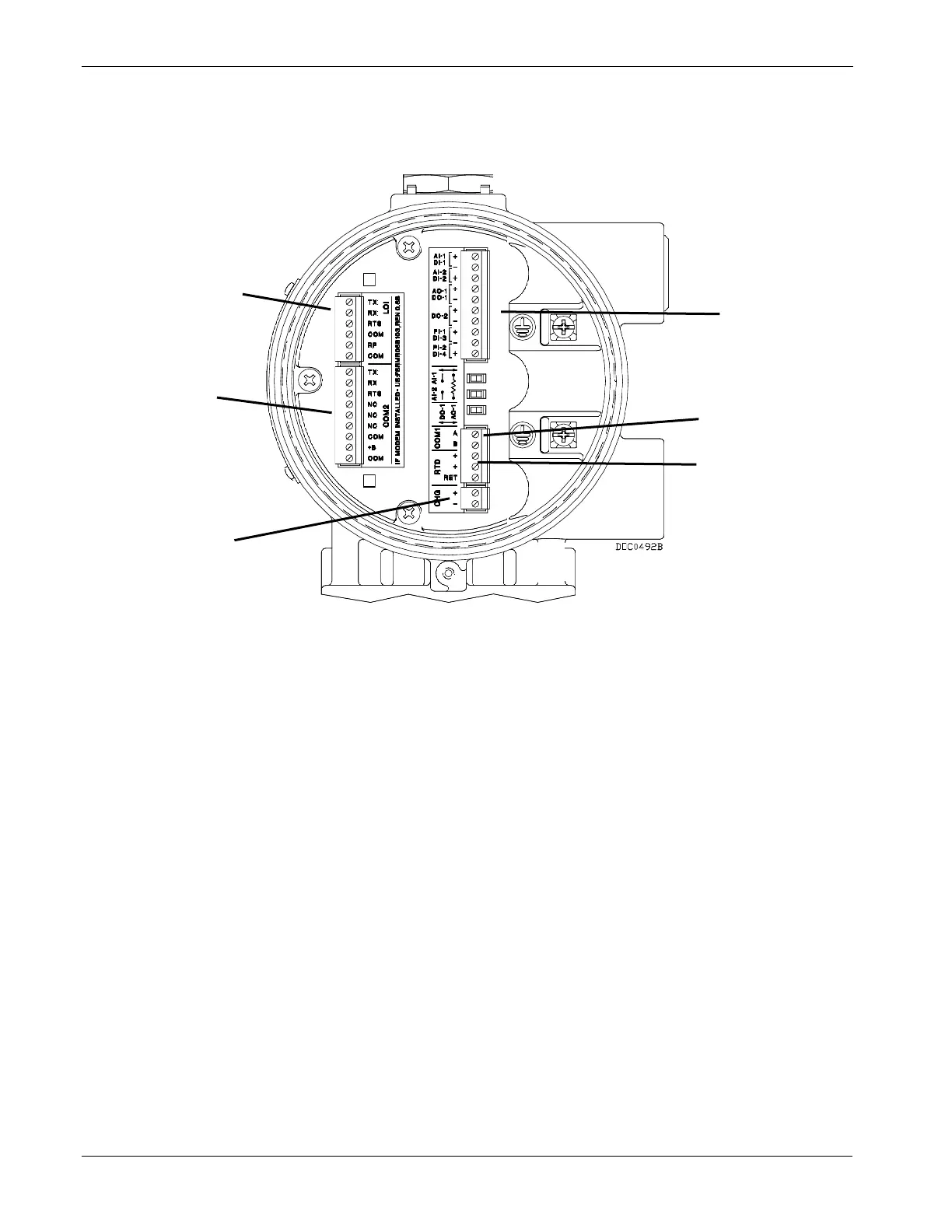
Located in the terminal side of the explosion-proof housing, the
termination module provides connections to the field wiring. Refer to
Figure 1-4.
Local operator interface (LOI)
Figure 1-4. Wiring Terminals
Connections include the power supply, Local Operator Interface (LOI)
communications, Comm 1 (for EIA-485 [RS-485] communications),
optional Comm 2 (for EIA-232 [RS-232], wireless spread-spectrum
radio, or dial-up modem communications), RTD wiring, and the I/O
field wiring.
The termination board provides surge and static discharge protection for
the field wiring. Electronics include the RTD circuits and the final I/O
drivers/receivers. The termination board also serves as an interface to
the backplane board in the electronics portion of the enclosure.
The 32-bit processor module (see Figure 1-3) contains the processor,
memory (static RAM, Flash EEPROM, and boot ROM), Local Operator
Interface (LOI) EIA-232 (RS-232) communications driver, Comm 1
EIA-485 (RS-485) communications driver, the reset controller, and the
real-time clock.
The processor module (also called the central processor unit or CPU)
provides the Serial Peripheral Interface (SPI) bus; the Liquid Crystal

 Loading...


