GFK-2738AE Jan 2024
4
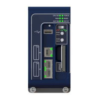
LEDs on the PROFINET Scanner Module
Power-Up LED Patterns
At power-up, the LEDs show the patterns described in the following table. The LEDs also blink diagnostic patterns
for certain operating errors and module identification.
OK LED blinks amber with a special
blink code
Fatal initialization or diagnostics failure;
H/W Module Identity Information not
available
STATUS LED blinks amber with a
special blink code
Fatal initialization failure
STATUS and LAN LEDs blink green
in unison (0.5 seconds ON/ 0.5
seconds OFF)
Internal update in the process following a
firmware update. The unit should complete
update and restart automatically
Normal operation. Power-up completed
Note: Under certain ambient operating temperatures, the PROFINET Scanner could momentarily display the
over-temperature pattern during power-up, while it is calibrating its thermal protection functions. This indication
can be ignored. For details, refer to the section entitled Microprocessor Over-Temperature in PACSystems RX3i
PROFINET Scanner Manual, GFK-2737.
 Loading...