Appendix 1 Circuit Diagram 17
7
6
J3 HP1 J4 HP2 J14 HP2 J15 HP1 J5 OutTemp
J11 RS232
J7 Fan1Sta J10 Fan2Sta J6 CompSta
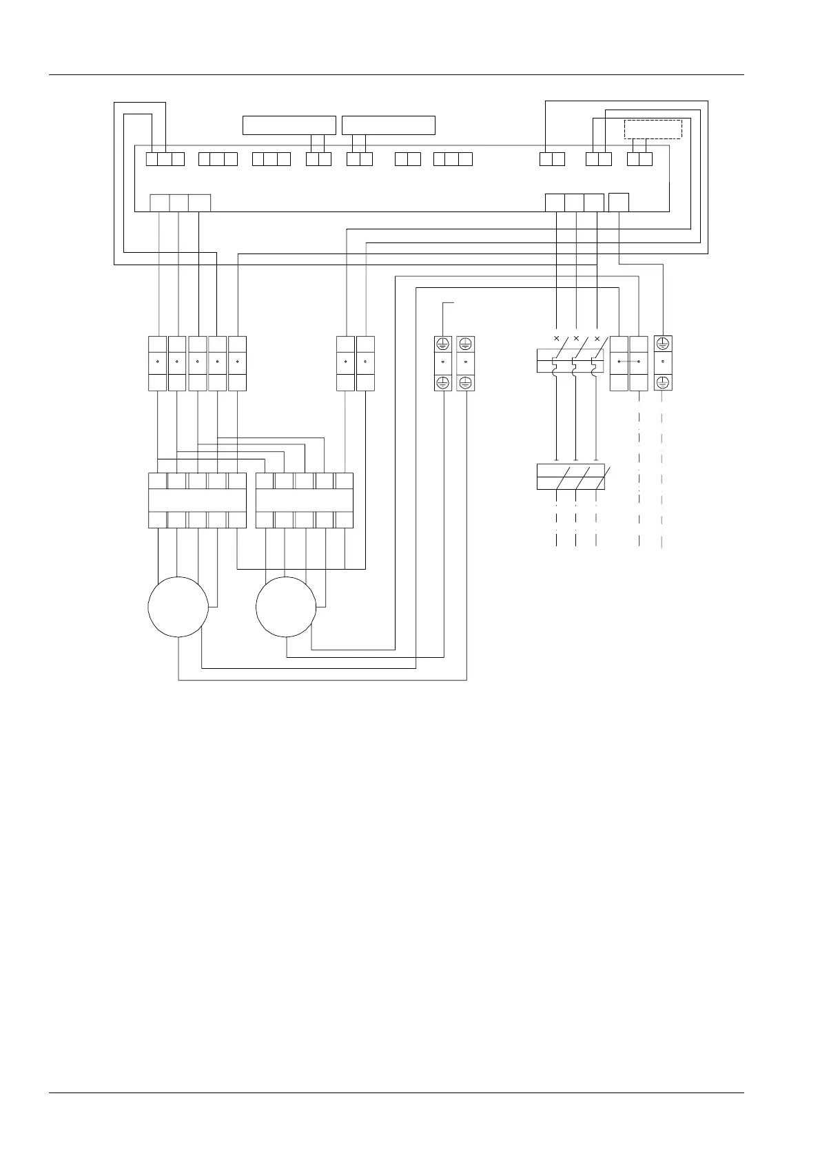
Remark:
1. Connect the pressure sensor 1 only, when PEX
condenser is a single circuit.
2. Connect the pressure sensor 1 and 2 with the
copper pipe of PEX condenser, when PEX
condenser is a dual circuit.
3. When mounted vertically, the lower header
connects to pressure sensor 1 and the upper
header connects to pressure sensor 2.
4. Both external power and compressor signal are
wired in field.
5. The compressor signal cables should be in
parallel and then connected into the electrical
control board, when the indoor unit is a dual circuit.
Air circuit
breaker
External power
Shell connecting
to the earth
Olivine
Black
White
Orange
Olivine
Black White
Orange Olivine
Brown
OlivineBrown
Black Orange Black Orange
Contactor 1
Contactor 2
Fan1 (remote)
Fan2
(proximal)
Wiring terminal
block
Compressor
White
Brown Orange
Isolation
switch
Black Black Black Black Black Black
Black Black Black
BlackBlack
Black Black Black
BlackBlack Black
BlackBlack Black
03
Pressure sensor 2
Black Black
L1
J9 3 2 1
Pressure sensor 1
06
10
11
W
UV
L3 L2 L1 PE
04 04 04 L1 06
12345
10 11
12 13
14
07 07 07 08 09
15 16
05
03 03
03
03
89
17 18
10 10 10
09 09 02 01 02 01
1L1
3L2 A1
5L3 NO 1L1
3L2 A1
5L3 NO
2T1 4T2 6T3 A2 NO 2T1 4T2 6T3 A2 NO
01 01 01
01
09 02 02 02 02 09
01
01
02
02
W1
V1
U1
TB
TB
PE
W1
V1
U1
TB
TB
PE
L3 L2 L1
N
PE
signal
Figure 2 Circuit diagram of the condenser with double fans
Liebert.PEX Condenser User Manual