EasyManua.ls Logo

Emerson Liebert PEX Series - User Manual

Emerson Liebert PEX Series
109 pages
To Next Page IconTo Next Page
Loading...
User Manual

Table of Contents

Questions and Answers:

Emerson Liebert PEX Series Specifications

General IconGeneral
BrandEmerson
ModelLiebert PEX Series
CategoryAir Conditioner
LanguageEnglish

Summary

Chapter 1 Overview

Model Description

Details the model description of the Liebert.PEX series air conditioner, including various configuration parameters.

Product Introduction

Provides an overview of the Liebert.PEX series air conditioner as a precision environment control system.

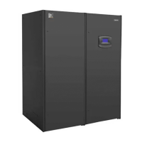
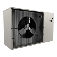
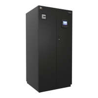
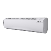
Product Appearance

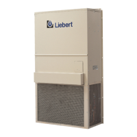
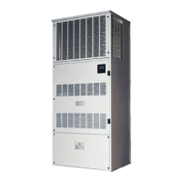
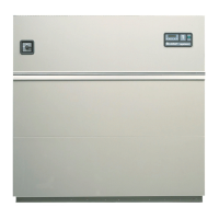
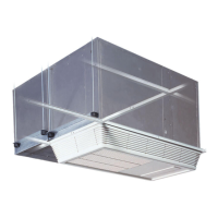
Illustrates the physical appearance of the Liebert.PEX series air conditioner, showing different unit configurations.

Main Components

Outlines the primary components of the Liebert.PEX air conditioner, including indoor unit, outdoor unit, and iCOM controller.

Chapter 2 Mechanical Installation

Movement, Unpacking, and Inspection

Details the procedures for safely moving, unpacking, and inspecting the air conditioner unit.

Installation Notes

Provides essential guidelines and considerations for a correct and optimal installation of the air conditioner.

System Installation Arrangement

Covers the overall system arrangement and illustrates installation modes for air-cooled and water-cooled series.

Installing Indoor Unit

Explains the requirements for the equipment room and the necessary installation space for the indoor unit.

Installing Outdoor Unit

References the manual for detailed installation instructions of the outdoor unit for air-cooled series.

Piping

Details piping procedures for air-cooled and water-cooled units, including pipe sizes and connections.

Lowering Fan and Removing Fixtures

Guides on lowering fans and removing transport fasteners and vibration absorbers for EC fan systems.

Installation Inspection

Lists items to check after mechanical installation is completed to ensure proper setup.

Chapter 3 Electrical Installation

Work Introduction and Installation Notes

Covers work introduction, installation notes, and wires to connect at site for electrical installation.

Wiring of Indoor Unit

Details locating electrical interfaces, connecting power, and control cables for the indoor unit.

Wiring of Outdoor Unit (For Air-Cooled Series)

Explains connecting control signal and power cables for the outdoor unit of air-cooled series.

Installation Inspection

Provides a checklist for inspecting electrical installation to ensure all connections and components are correct.

Chapter 4 System Power-On Commissioning

Location of MCBs

Identifies the locations of Miniature Circuit Breakers (MCBs) within the electrical control box.

Power-On Commissioning Of Air-Cooled Series

Details preparation, commissioning procedures, and inspection after commissioning for air-cooled series units.

Power-On Commissioning Of Water-Cooled Series

Outlines preparation, commissioning procedures, and inspection after commissioning for water-cooled series units.

Chapter 5 iCOM Controller

LCD

Describes the Liquid Crystal Display (LCD) on the front panel for monitoring and configuration.

Button And Indicator Panel

Explains the function of buttons and indicators on the iCOM controller's interface panel.

Structure Chart Of Control Menu

Refers to Appendix 3 for the menu structure of the iCOM Controller.

Startup Interface

Shows the initial interface displayed on the LCD after the system is powered on.

Main Interface

Details the general equipment status displayed on the LCD, including temperature, humidity, and system status.

USER MENUS

Describes the user-accessible menus for monitoring and adjusting system parameters.

SERVICE MENUS

Outlines advanced service menus for professional personnel to configure and diagnose the system.

ADVANCED MENUS

Covers password level, factory setup, and password management within advanced system settings.

MBV Settings

Details settings related to the Motorized Ball Valve (MBV) for system control.

Event Name and Definition

Lists and defines various event names and their corresponding meanings for system monitoring.

Chapter 6 Application Of INTELLISLOT

Introduction Of Host Communication Cards

Introduces TCP/IP and 485 communication cards for host communication.

Installation Of Host Communication Cards

Provides instructions for installing host communication cards into the air conditioner unit.

Commission Of Host Communication Component

Details commissioning procedures for HyperTerminal, 485, and TCP/IP communication cards.

Host Communication Networking Diagram

Illustrates networking diagrams for TCP/IP and 485 communication cards.

Chapter 7 System Operation And Maintenance

System Diagnosing Test

Explains system diagnosing tests, including self-diagnosis function and electric control part checks.

Filter

Details filter inspection, replacement, and setpoint adjustment for optimal system operation.

Fan Components

Covers maintenance checks for FC and EC fan components, including bearings, belts, and motors.

Infrared Humidifier

Provides guidance on cleaning the water pan and replacing lamps for the infrared humidifier.

Electric Heater

Describes checks for electric heaters, including temperature switches and potential faults.

Cooling System

Details checks for cooling system components like suction pressure, discharge pressure, and superheat degree.

Compressor

Guides on compressor maintenance, fault diagnosis, and replacement procedures.

Chapter 8 Troubleshooting

Fan Fault Removal

Troubleshooting guide for fan failures, including power supply, circuit breakers, and motor issues.

Compressor and Cooling System Troubleshooting

Addresses issues related to compressor startup, cooling system pressures, and refrigerant.

Troubleshooting of Infrared Humidifier

Details troubleshooting steps for infrared humidifier issues like no water or contactor failure.

Troubleshooting of Heating System

Covers troubleshooting for heating system failures, including demand, relays, and safety devices.

Appendix 1 Composition Of Electrical Control Box

Appendix 2 Circuit Diagram

Appendix 3 Menu Structure Of iCOM Controller

Related product manuals