36 Chapter 3 Electrical Installation
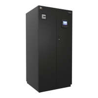
Field connection terminal block
Power
supply
connection
Figure 3-2 Electrical control box interfaces of two-bay unit
Note
The two-bay series with single compressor has only one compressor MCB and a contactor.
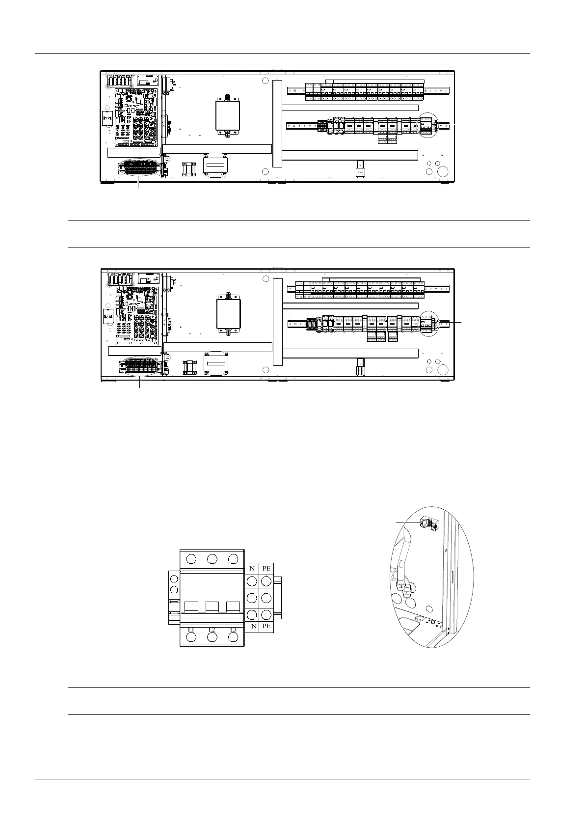
Power
supply
connection
Field connection terminal block
Figure 3-3 Electrical control box interfaces of three-bay unit
3.2.2 Connecting Power Cable Of Indoor Unit
The power interfaces are located as shown in Figure 3-1, Figure 3-2 and Figure 3-3. The amplified figure of the power
interface is shown in Figure 3-4. Connect terminals L1 ~ L3, N, and PE to their counterparts of external power supply.
Fix the input cables to the cable clamp, note that the cable clamp is located on the inner side panel of the unit, see
Figure 3-5 for its position. For the cable specification, see the rated full load ampere (FLA) listed in Table 3-1.
Cable clamp
Figure 3-4 Amplified figure of main input isolation switch and
terminals
Figure 3-5 Cable clamp
Note
The cable sizes should meet the local wiring regulations.
Liebert.PEX2 Series Air Conditioner User Manual

 Loading...