This document describes the Micro Motion® Gas Density Meter (GDM), a device designed for fiscal gas density measurement. It provides comprehensive information on planning, mounting, wiring, and grounding the meter, ensuring proper installation and operation.
Function Description
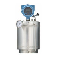
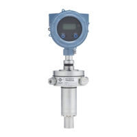
The Micro Motion GDM is used for accurate gas density measurement, particularly in fiscal applications such as orifice plate metering systems, vented gas applications, and installations with ultrasonic or turbine flow meters. The device measures gas density by sampling a small portion of the main gas flow. This density measurement is crucial for calculating mass flow rates in conjunction with other flow measurement devices, adhering to international standards like ISO 5167 and AGA 3. The meter is designed to maintain a sample gas flow rate representative of the main flow, ensuring accuracy in the proportions of different gas constituents.
Important Technical Specifications
Power Requirements:
- DC Power: 24 VDC, 0.45 W maximum.
- Minimum Voltage: 22.8 VDC with 1000 m (3280 ft) of 0.20 mm² (18 AWG) power-supply cable.
- Startup Current: Minimum 0.5 A of short-term current at a minimum of 19.6 V at the power-input terminals.
- Wire Gauge: The manual provides a graph for minimum wire gauge (AWG per feet) based on distance of installation and voltage (22.8V and 24V), indicating that for longer distances, a lower AWG (thicker wire) is required to maintain voltage. For example, at 3000 ft, an 18 AWG wire is needed for 22.8V, while a 14 AWG wire is needed for 24V.
Sample Flow Rate:
- Recommended: 5 ±1 l/hr (0.176 ±0.35 ft³/hr).
- Acceptable Range: 1 to 10 l/hr (0.035 to 0.35 ft³/hr).
- Impact of Higher Flow Rates: Flow rates greater than 10 l/hr (0.35 ft³/hr) can lead to slightly unstable density readings and small density errors.
- Pressure Differential: For natural gas with a typical density of 0.06 g/cm³ (60 kg/m³), a pressure differential of approximately 1.66 mbar (0.67 in WC) is required to maintain a flow rate of 5 l/hr (0.176 ft³/hr).
Physical Dimensions (Thermo-well pocket):
- Overall Length: 6.00 inches (152.30 mm).
- Flange Diameter: Ø3.94 inches (100.00 mm).
- Mounting Base Diameter: 2.83 inches (72.00 mm).
- Insertion Depth: 1.59 inches (40.30 mm).
Output Terminals and Wiring Requirements:
The meter offers various output options depending on the transmitter version:
- Analog (mA): 4-20 mA + HART, 4-20 mA.
- Time Period Signal (TPS): Available as a discrete output.
- Modbus/RS-485: For digital communication.
- Maximum Wire Size: 14 AWG (2.5 mm²) for all output terminals.
Hazardous Area Entity Parameters (for intrinsically safe installations):
- Power Supply: Voltage (Ui) 30 VDC, Current (Ii) 484 mA, Power (Pi) 2.05 W, Internal capacitance (Ci) 0.0 pF, Internal inductance (Li) 0.0 H.
- 4-20 mA / Discrete Output / Time Period Signal: Voltage (Ui) 30 VDC, Current (Ii) 484 mA, Power (Pi) 2.05 W, Internal capacitance (Ci) 0.0 pF, Internal inductance (Li) 0.0 H.
- RS-485: Voltage (Ui) 18 VDC, Current (Ii) 484 mA, Power (Pi) 2.05 W, Internal capacitance (Ci) 0.0011 pF, Internal inductance (Li) 0.0 H.
- RS-485 Output Parameters (MTL7761AC): Voltage (Uo) 9.51 VDC, Current (Io) 480 mA (instantaneous), 106 mA (steady state), Power (Po) 786 mW, Internal resistance (Ro) 19.8 Ω.
- Cable Parameters for Group IIC: External capacitance (Cc) 85 nF, External inductance (Lc) 154 µH, External inductance/resistance ratio (Lc/Rc) 31.1 µH/Ω.
- Cable Parameters for Group IIB: External capacitance (Cc) 660 nF, External inductance (Lc) 610 µH, External inductance/resistance ratio (Lc/Rc) 124.4 µH/Ω.
Usage Features
Installation Flexibility:
- Mounting: The meter can be mounted in a pipeline, typically using a thermo-well pocket. The electronics can be rotated up to 90° for optimal viewing.
- Display Rotation: The display on the transmitter electronics module can be rotated 90° or 180° from its original position for better visibility.
- Gas Bypass Lines: The meter includes two filters for gas connection ports: a 2-micron filter for the inlet and a 90-micron filter for the outlet, ensuring optimal performance and protection against reverse gas flow.
- Application-Specific Installations: Recommended installations for various gas density applications, including:
- Orifice Plate Metering System (Pressure Recovery Method): Density is measured downstream from the orifice plate, allowing optimal gas flow and easy access for filter checks and calibration verification. No bypass of the orifice plate is necessary.
- Differential Pressure Application (Upstream Installation): An alternative method where the sample gas flow bypasses the orifice plate.
- Vented Gas Application: Gas is vented to flare or atmosphere, utilizing full-pipe pressure as a pressure drop. A two-stage letdown system may be required for high-pressure applications to prevent icing.
- Ultrasonic Meter Application: Installed downstream from an ultrasonic meter, often with a Rosemount Annubar® flowmeter to provide differential pressure.
- Turbine Flow Meter Application: Integrated into a system with a gas turbine flowmeter.
Safety and Approvals:
- European Directives: Complies with all applicable European directives when properly installed. EC declarations of conformity and ATEX Installation Drawings are available online.
- Pressure Equipment Directive: Information available online.
- Hazardous Installations: For Europe, EN 60079-14 is referenced. For IECEx installations, IEC 60079-14 is applicable. In the U.S.A. and Canada, ISA 12.06.01 Part 1 provides guidelines.
- Safety Barriers/Galvanic Isolators: Required for hazardous area installations, with specific kits available for different output types (4-20 mA, TPS/Discrete, Modbus/RS-485, Power).
Maintenance Features
Pre-Installation Check:
- Shipment Verification: Confirm all parts and information are present.
- Environmental Suitability: Ensure local ambient/process temperatures and pressure are within meter limits.
- Hazardous Area Compliance: Verify the specified hazardous area on the approval tag is suitable.
- Physical Inspection: Visually inspect for any damage.
- Known Density Verification (KDV): A procedure to match current meter calibration with factory calibration, ensuring no drift during shipment.
Best Practices for Installation and Operation:
- Handling: Handle the meter with care.
- Process Gas Quality: Ensure the process gas is clean and dry.
- Material Compatibility: Do not use gases incompatible with the materials of construction.
- Vibration: Avoid excessive vibration (greater than 0.5 g continuously).
- Temperature Equilibrium: Install the meter in a thermo-well pocket to ensure temperature equilibrium between the sample gas and pipeline gas.
- Sample Volume/Response Time: Minimize the length and volume of the input sample pipe to ensure an optimal meter response time (use 6 mm (1/4 in) instrument tubing and low-volume inlet filters).
- Flow Control: Control gas flow with a needle valve mounted before or after the meter.
- Coalescing Filter: Install an external coalescing filter in the sample gas inlet pipework to minimize condensate and dust contamination.
- Pressure Verification: Verify that the pressure of the process gas is approximately equal to the pipeline pressure.
- Cross-Sectional Area: Do not exceed more than a 10% reduction of the cross-sectional area at the point of insertion in the pipeline to ensure minimal effect on pressure.
- Pressure Test: Ensure that the meter and associated pipework are pressure-tested to 1½ times the maximum operating pressure after installation.
- Thermal Insulation: Install thermal insulation to the meter and the inlet and bypass-loop pipeline to maintain temperature equilibrium. Maintain a nominal 1-inch clearance between insulation and the transmitter housing. Do not insulate the transmitter (electronics).
Grounding:
- Standards Compliance: Ground the meter according to applicable site standards (EN 60079-14, ISA 12.06.01 Part 1).
- Wiring Guidelines: Use copper wire, 18 AWG (0.75 mm²) or larger, keep ground leads as short as possible (< 1 Ω impedance), and connect directly to earth or follow plant standards.
- Pipeline Grounding: If pipeline joints are ground-bonded, the sensor is automatically grounded. Otherwise, connect a ground wire to the grounding screw on the sensor electronics.
Customer Support:
- Return Policy: Micro Motion procedures must be followed for equipment returns to ensure legal compliance and a safe working environment.
- Technical Support: Contact Micro Motion Customer Service via email (flow.support@emerson.com for worldwide, APflow.support@emerson.com for Asia-Pacific) or telephone for assistance with damaged meters, KDV checks, or barrier/isolator kits.