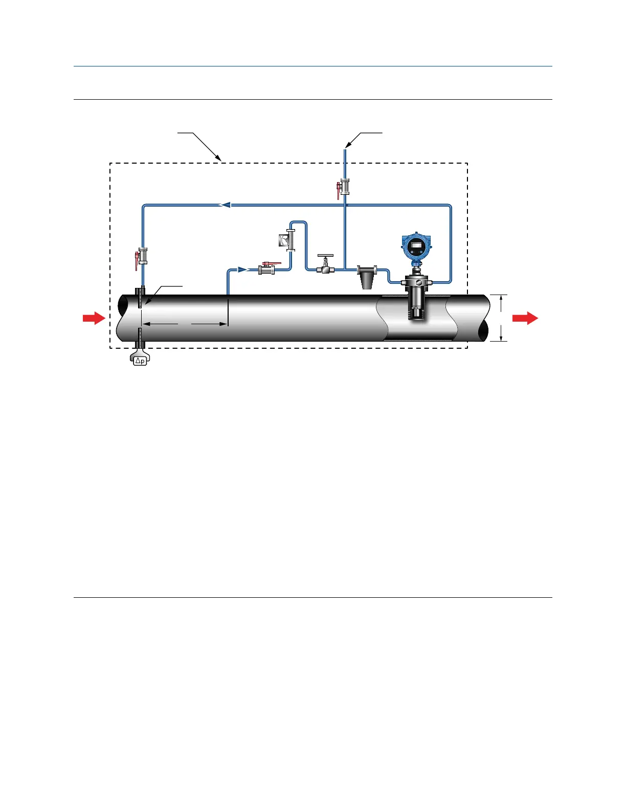
Meter installation in pressure recovery applicationFigure 1-5:
STATUS
SCROLL SELECT
C
A
E
A
B
D
G
F
H
J K
I
GDM
A. Meter isolation valves
B. Flowmeter
C. Venting valve
D. Flow control needle valve
E. Filter
F. Pipeline diameter
G. Differential pressure transmitter
H. Density point
I. Distance is eight times the pipeline diameter
J. Thermal insulation
K. Vent/vacuum test point
Note
Do not insulate the transmitter (electronics) and maintain a nominal 1-in clearance between the insulation and the transmitter
housing.
With the pressure recovery installation method:
• No bypass of the orifice plate is necessary.
• Density is measured at the downstream tapping of the orifice plate, which reduces
the significance of pressure build-up across the fine-gauge filters.
• Flow is achieved because the pressure after the orifice plate is lower than that
further downstream.
Planning
8 Micro Motion
®
Gas Density Meters