• Twisted pair construction.
• Applicable hazardous area requirements, if the core processor is installed in a
hazardous area.
• Wire gauge appropriate for the cable length between the core processor and the
transmitter, or the host.
Table 3-2: Wire gauge
Wire gauge Maximum cable length
VDC 22 AWG (0.326 mm²) 300 ft (91 m)
VDC 20 AWG (0.518 mm²) 500 ft (152 m)
VDC 18 AWG (0.823 mm²) 1,000 ft (305 m)
RS-485 22 AWG (0.326 mm²) or larger 1,000 ft (305 m)
3.2.2 Prepare a cable with a metal conduit
Procedure
1. Remove the core processor cover using a flat-blade screw driver.
2. Run the conduit to the sensor.
3. Pull the cable through the conduit.
4. Cut the drain wires and let them float at both ends of the conduit.
3.2.3
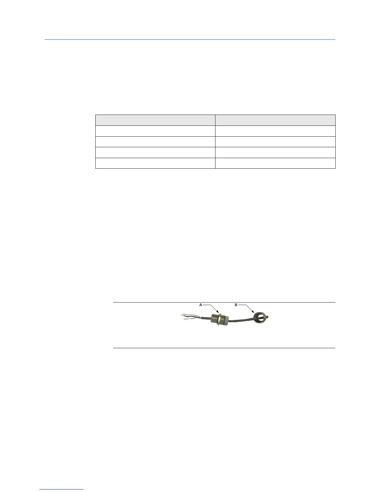
Prepare a cable with user-supplied cable glands
Procedure
1. Remove the core processor cover using a flat-blade screw driver.
2. Pass the wires through the gland nut and gland body.
A. Gland body
B. Gland nut
3. Terminate the RS-485 shield and drain wires to the housing internal grounding
screw.
4. Assemble the gland according to vendor instructions.
3.2.4
Prepare a cable with Micro Motion-supplied cable glands
Procedure
1. Remove the core processor cover using a flat-blade screw driver.
2. Pass the wires through the gland nut and clamping insert.
Transmitter power and I/O wiring Installation Manual
January 2019 20002346
14 Micro Motion H-Series
 Loading...