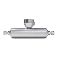
A. Gland nut
B. Clamping insert
3. Strip the cable jacket.
Option Description
NPT gland type Strip 4.5 in (114 mm)
M20 gland type Strip 4.25 in (108 mm)
4. Remove the clear wrap and filler material.
5. Strip most of the shielding.
Option Description
NPT gland type Strip all but 0.75 in (19 mm)
M20 gland type Strip all but 0.5 in (13 mm)
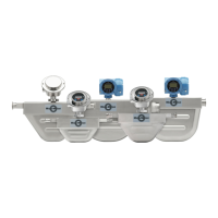
6. Wrap the drain wires twice around the shield and cut off the excess drain wires.
A. Drain wires wrapped around shield
7. For foil (shielded cable) only:
Note
For braided (armored cable) skip this step and contine to the next step.
Option
Description
NPT
gland
type
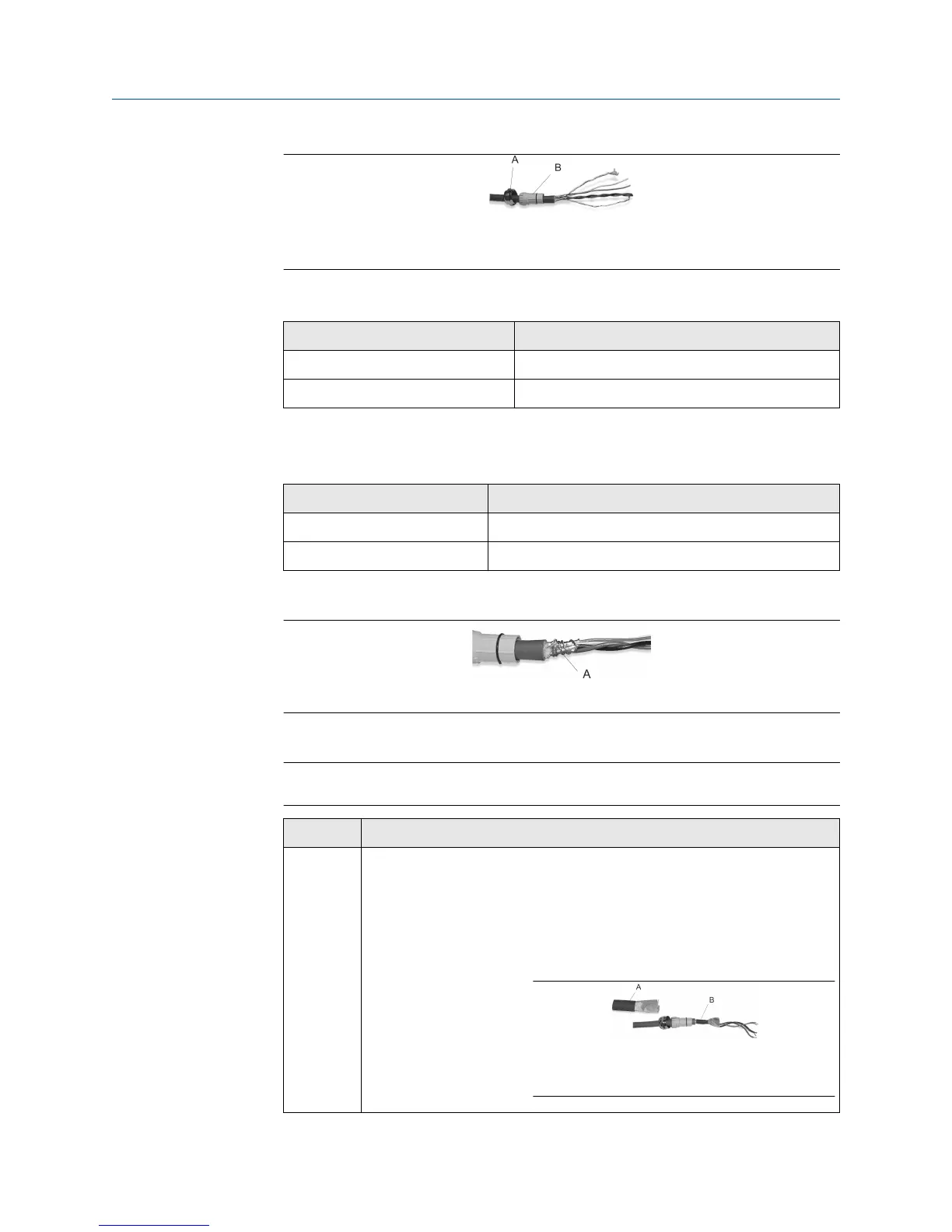
a. Slide the shielded heat shrink over the drain wires. Ensure that
the wires are completely covered.
b. Apply 250 °F (121.1 °C) heat to shrink the tubing. Do not burn
the cable.
c. Position the clamping insert so the interior end is flush with the
braid of the heat shrink.
A. Shielded heat shrink
B. After heat is applied
Installation Manual Transmitter power and I/O wiring
20002346 January 2019
Installation Manual 15
 Loading...