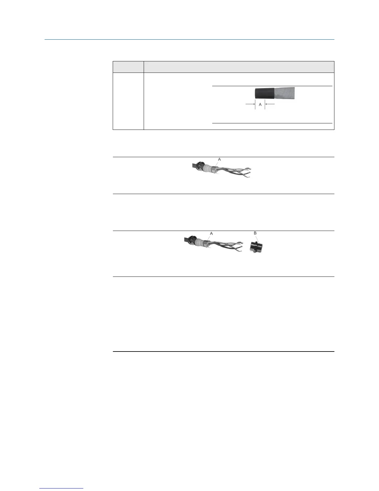
Option Description
M20
gland
type
Trim 0.3 in (8 mm).
A. Trim
8. Assemble the gland by folding the shield or braid back over the clamping insert and
0.125 in (3 mm) past the O-ring.
A. Shield folded back
9. Install the gland body into the conduit opening on the core processor housing.
10. Insert the wires through the gland body and tighten the gland nut onto the gland
body.
A. Shield folded back
B. Gland body
3.2.5
Connect the wires to the core processor terminals
After the 4-wire cable has been prepared and shielded (if required), connect the individual
wires of the 4-wire cable to the terminals on the core processor.
Procedure
1. Connect the wires to the core processor terminals.
2. Reinstall the core processor cover.
3. Torque the cover screws to:
• 10 in lbf (1.13 N m) to 13 in lbf (1.47 N m) for an aluminum housing
• minimum 19 in lbf (2.15 N m) for a stainless steel housing
If properly seated, there will be no gap between cover and base.
4. Connect the wires to the transmitter terminals using the transmitter installation
manual.
Transmitter power and I/O wiring Installation Manual
January 2019 20002346
16 Micro Motion H-Series
 Loading...