22 Micro Motion
®
Model D and DT Sensors Instruction Manual
Wiring continued
1. Locate the wires by color and terminal number.
2. Insert the stripped ends of the individual wires into the terminal
blocks. No bare wires should remain exposed.
• At the sensor, connect wiring inside the junction box.
• At the transmitter, connect wiring to the transmitter’s intrinsically
safe terminals for sensor wiring.
3. Tighten the screws to hold the wires in place.
4. Ensure integrity of gaskets, then tightly close and seal the
junction-box cover and all housing covers on the transmitter.
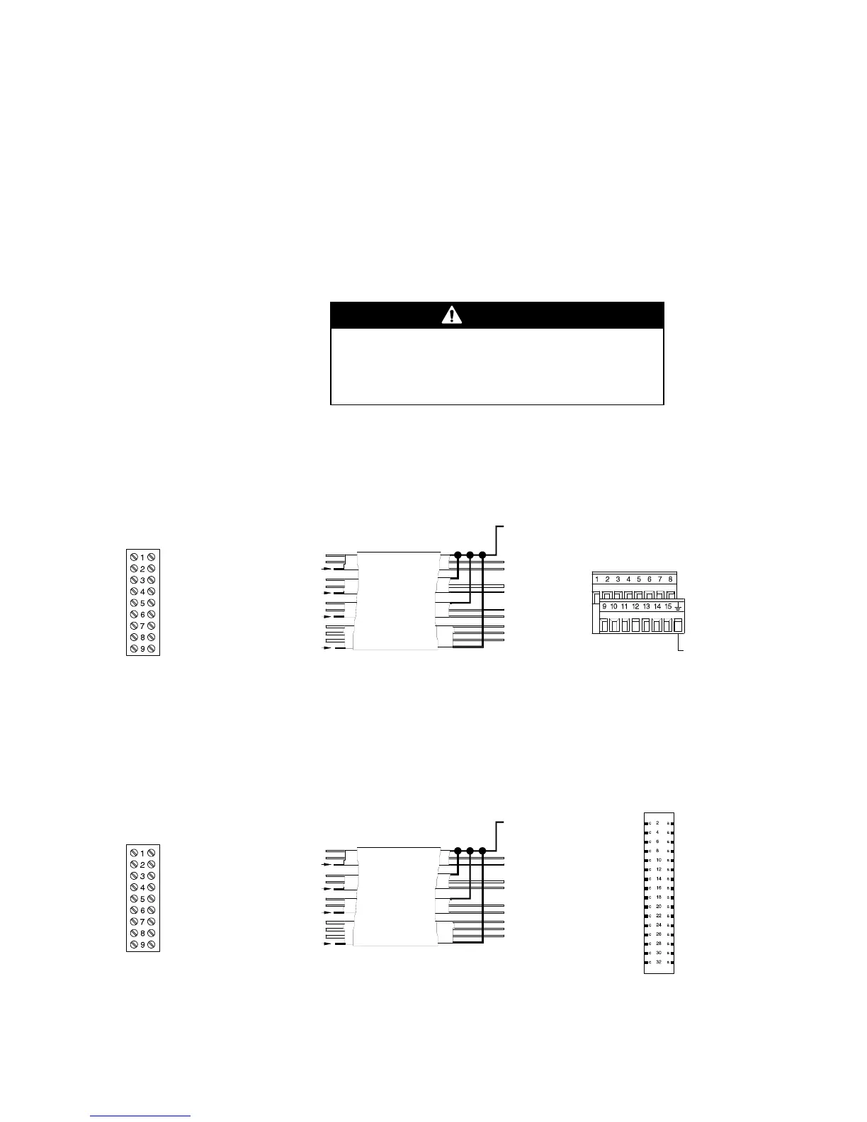
Model D or DT sensor (except D600) wiring to Model 3500 with I/O cable
Model D or DT sensor (except D600) wiring to Model 3500 with screw or solder terminals
Drain wires from a 9-wire cable must be clipped at the
sensor end and insulated with heat-shrink wrapping.
Failure to properly terminate drain wires will cause
sensor error.
Brown
Red
Clip drain wire back
Green
White
Clip drain wire back
Blue
Gray
Clip drain wire back
Orange
Violet
Yellow
Clip drain wire back
Model D or DT
sensor terminals
Flowmeter
cable
Brown
Red
Green
White
Blue
Gray
Orange
Violet
Ye l l o w
Black
(Drains from all
wire sets)
Maximum cable length 1000 ft. (300 m)
Prepare cable in accordance with the instructions
that are shipped with the cable
Brown
Red
Orange
Yellow
Green
Blue
Violet
Gray
White
Brown
Red
Orange
Ye l l o w
Green
Blue
Violet
Gray
White
Black (drains)
Connect outer
braid of shielded or
armored cable
For DT sensor junction box
information, see page 20.
Model 3500
with I/O cable
Not approved for intrinsic safety
in Europe
Brown
Red
Clip drain wire back
Green
White
Clip drain wire back
Blue
Gray
Clip drain wire back
Orange
Violet
Yellow
Clip drain wire back
Model D or DT
sensor terminals
Flowmeter
cable
Model 3500
with screw-type or
solder-tail terminals
Brown
Red
Green
White
Blue
Gray
Orange
Violet
Ye l l o w
Black
(Drains from all
wire sets)
Yellow
Violet
Green
Blue
Brown
Black (Drains)
Orange
White
Gray
Red
Maximum cable length 1000 ft. (300 m)
Prepare cable in accordance with the instructions
that are shipped with the cable
c4
c6
c8
c10
c12
a4
a6
a8
a10
a12
Brown
Red
Orange
Yellow
Green
Blue
Violet
Gray
White
For DT sensor junction box
information, see page 20.