48 Micro Motion
®
Model D and DT Sensors Instruction Manual
Troubleshooting continued
c. Use a DMM to measure resistance across wire pairs at the
transmitter end of the cable. See table on page 48.
• If the measured value is within the range listed in the table,
reconnect wiring and restore power to the transmitter.
• If the measured resistance is outside the range listed in the table,
repeat the measurements at the sensor junction box.
- If the sensor is a not a D600, refer to the “Nominal resistance
ranges” table below.
- If the sensor is a D600, refer to the table and illustration on
page 49.
- If resistance values measured at the sensor are also outside the
range listed in the table, the sensor might be faulty.
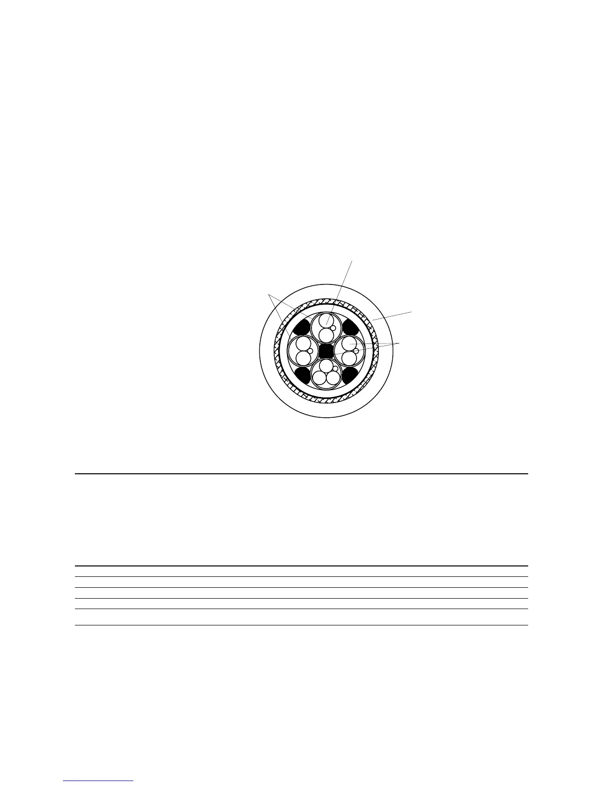
Cross-section of cable with drain wires
Table 6. Nominal resistance ranges for flowmeter circuits (for all D and DT sensors except the D600)
Notes
• Disconnect wires from terminals before checking resistance values.
• Temperature-sensor value increases 0.38675 ohms per °C increase in temperature.
• Nominal resistance values will vary 40% per 100°C. However, confirming an open coil or shorted coil is more important than
any slight deviation from the resistance values presented below.
• Resistance across blue and gray wires (right pickoff circuit) should be within 10% of resistance across green and white wires
(left pickoff circuit).
• Actual resistance values depend on the sensor model and date of manufacture.
• Reading across wire pairs should be steady.
Circuit Wire colors Sensor terminals* Nominal resistance range
Drive coil Brown to red 1 to 2 8 to 2650 Ω
Left pickoff Green to white 5 to 9 16 to 300 Ω
Right pickoff Blue to gray 6 to 8 16 to 300 Ω
Temperature sensor Orange to violet 3 to 7 100 Ω at 0°C + 0.38675 Ω / °C
Lead length compensator Yellow to violet 4 to 7 100 Ω at 0°C + 0.38675 Ω / °C
* For transmitter terminal designations, refer to the table below. For D600 sensors, see the illustration and table on page 49.