Micro Motion
®
Model D and DT Sensors Instruction Manual 49
Troubleshooting continued
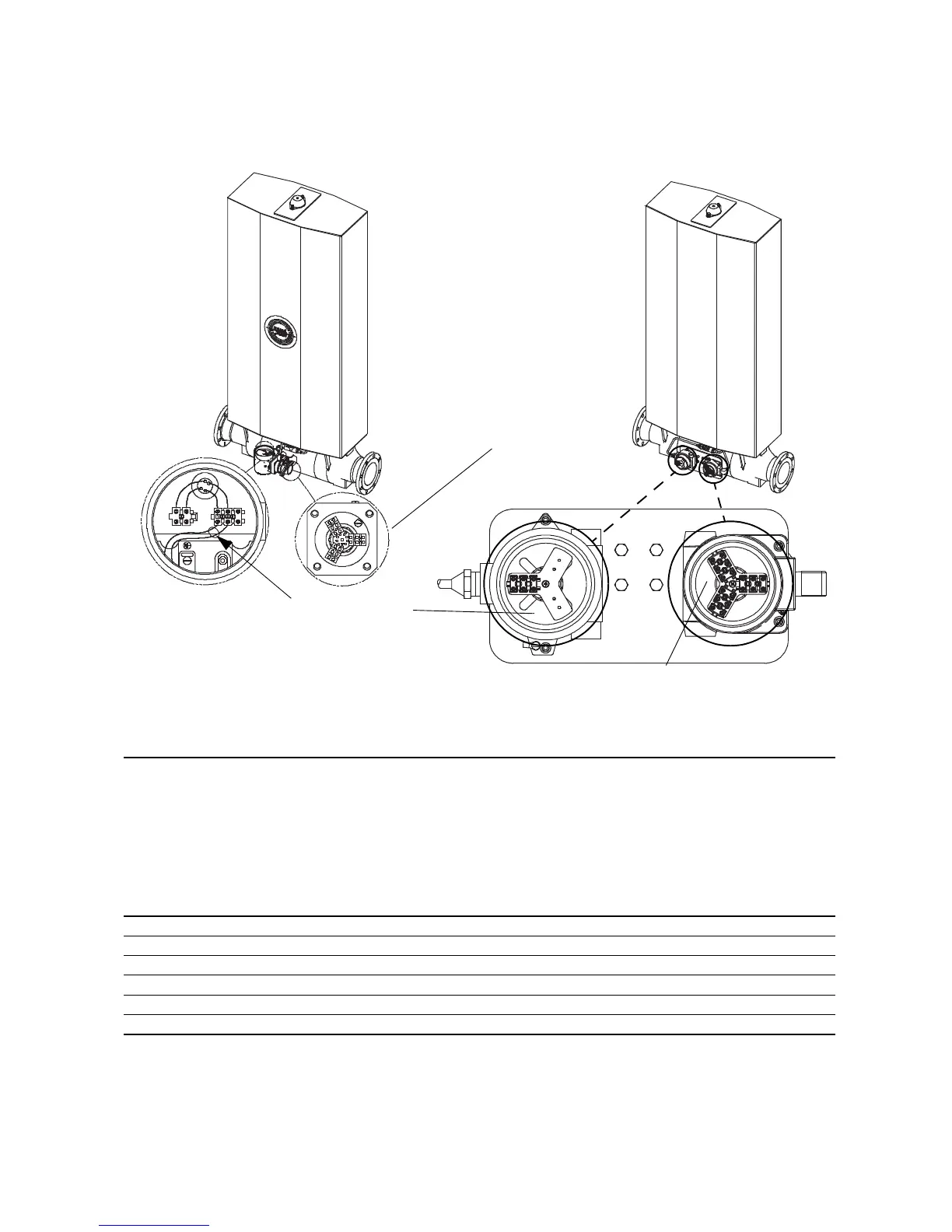
Checking ohm levels at a D600 sensor (applicable only to sensors with a junction box)
Check drive coil circuit, brown to red here
Check all circuits except
drive coil circuit (brown to
red wires) here
D600 sensor with integral booster amplifier
D600 sensor with remote mounted booster amplifier
(booster amplifier not shown)
Check all circuits except drive coil circuit (brown to red wires) here
Table 7. Nominal resistance values for D600 circuits
Notes
• Disconnect wires from terminals before checking resistance values.
• Temperature-sensor value increases 0.38675 ohms per °C increase in temperature.
• Nominal resistance values will vary 40% per 100°C. However, confirming an open coil or shorted coil is more important than
any slight deviation from the resistance values presented below.
• Resistance across blue and gray wires (right pickoff circuit) should be within 10% of resistance across green and white wires
(left pickoff circuit).
• Actual resistance values depend on the sensor model and date of manufacture.
• Reading across wire pairs should be steady.
• See previous illustration for terminal locations.
Circuit Wire colors Approximate nominal resistance
Drive coil Brown to red 16 Ω
Primary left pickoff Green to white 140 Ω
Primary right pickoff Blue to gray 140 Ω
Secondary left pickoff Brown to white 140 Ω
Secondary right pickoff Red to gray 140 Ω
Temperature sensor Yellow to violet 100 Ω at 0°C + 0.38675 Ω / °C