Dry-run Configuration
November 2019
Safety Manual
00809-0400-5100, Rev AB
36
Dry-run Configuration
4. Specify and configure the Low Alarm Limit.
5. Ensure that the Amplitude Threshold is less than
25% of the amplitude of the Product Surface
echo. The default value is 400 mV.
Note! The product surface should be slightly
below the Low Alarm Limit in the Tank. There
are two reasons for this:
a) calibration should be performed at this point
in the Tank to ensure highest accuracy at the
Low Alarm Limit
b) to make sure that appropriate Amplitude
Thresholds will be set based on the signal
strength at this point
6. Check the Tank Scan window to get an overview
of how much noise that exists in the Near Zone
region, the region below the Hold Off Distance.
Tip! To open Tank Scan: right-click the
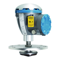
Rosemount 5900 icon and select
Properties>Advanced Configuration>Tank Scan.
7. Filter out noise in the Near Zone region by
adding an ATP curve in TankMaster. The ATP
should be approximately four times the
amplitude of the noise amplitude.
8. Click the Apply button in order to download the
ATP to the Rosemount 5900 level gauge.
1. To open the Tank Scan window: in TankMaster WinSetup, right-click the 5900 gauge icon, choose Properties, select the Advanced Configuration tab
and click the Tank Scan button.
2. To set the Hold Off Distance: in TankMaster WinSetup, right-click the 5900 gauge icon, choose Properties, select the Antenna tab.
Distance
Amplitude
A
C
B
A. Amplitude threshold
B. High Alarm Limit
C. Product surface
D. Minimum operation distance
E. Hold Off Distance
F. Measurement range
G. Low Alarm Limit
E
D
G
F
Distance
Amplitude
A
C
B
A. Amplitude threshold
B. High Alarm Limit
C. Product surface
D. Minimum operation distance
E. Hold Off Distance
F. Measurement range
G. Low Alarm Limit
H. Amplitude Threshold Point (ATP)
D
E
H
F
G
 Loading...


