00809-0100-4835 Rev BE
OPERATION
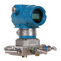
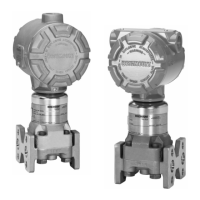
The block diagram in Figure 4-1 illustrates the operation of
the 3150 Series pressure transmitter.
The 3150 Series pressure transmitters have a variable
capacitance sensor (see Figure 4-2). Differential capacitance
between the sensing diaphragm and the capacitor plates is
converted electronically to a 2-wire, 4-20 mA dc signal based
on the following formulas:
=
+
Where:
P is the process pressure.
k
1
is a constant.
C
1
is the capacitance between the high-pressure
side and the sensing diaphragm.
C
2
is the capacitance between the low-pressure
side and the sensing diaphragm.
=
+
Where:
I
ref
is the reference current.
V
p-p
is the peak to peak oscillation voltage.
f is the oscillation frequency.
=
(
)
Where:
I
diff
is the difference in current between C
1
and
C
2
.
Therefore:
=
=
+





 To Next Page