00809-0100-4835 Rev BE
Maintenance & Troubleshooting
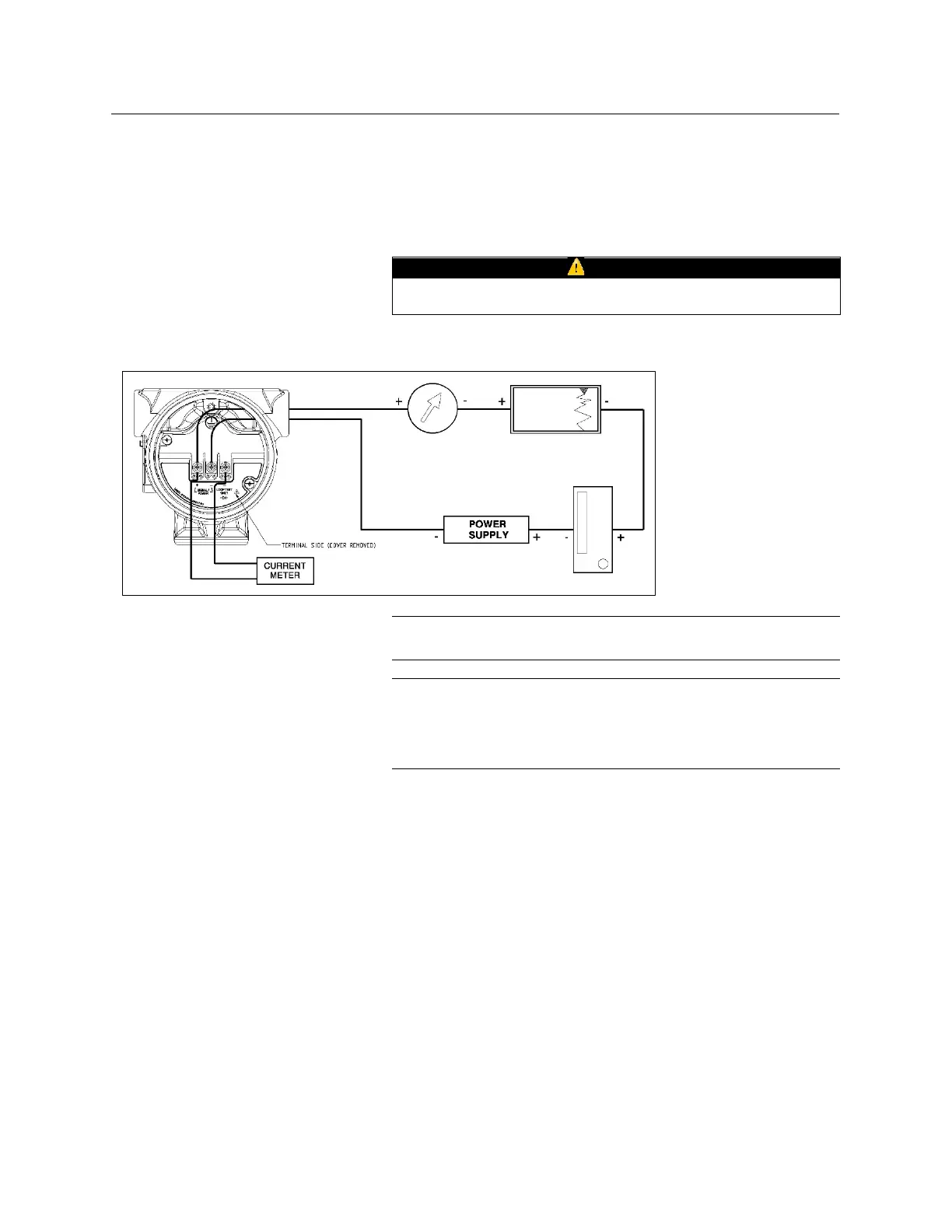
A test terminal is provided to allow connection of a current
meter without impacting the powered signal loop. As shown in
Figure 5-2, the current meter is connected from the positive
signal terminal to the loop test terminal. Proper function of the
test terminal requires that the internal resistance of the current
meter be no more than 10 ohms.
Incorrect wiring of the test terminal may result in damage to
the transmitter.
Figure 5-2 – Connection of Current
Meter to Test Terminals
ELECTRONICS ASSEMBLY
CHECKOUT
NOTE
Numbers in parentheses refer to item numbers in
.
3150 Series transmitters contain electronic circuit boards
which may be static sensitive. Therefore, observe proper ESD
precautions/techniques whenever the electronics assemblies
are handled and/or uncovered.
The electronics assembly (4) is not field-repairable and must
be replaced if defective.
To check the electronics assembly for a malfunction,
substitute a spare assembly into the transmitter using the
procedures in this section.
To remove the existing electronics assembly, refer to the
steps outlined in the Electrical Housing Disassembly
section.
To install the new electronics assembly, refer to the steps
outlined in Electrical Housing Reassembly section.
If this procedure reveals a malfunctioning assembly, return the
defective assembly to Rosemount Nuclear for replacement.
See Important Notice regarding field repair at the beginning of
 Loading...


