36 Commander SK Getting Started Guide
www.controltechniques.com Issue Number: 9
0: Coast to stop selected
1: Ramp to stop selected
2: Ramp to stop with 1 second DC injection braking
3: DC injection braking with detection of zero speed
4: Timed DC injection braking
See the Commander SK Advanced User Guide.
OFF:Fixed linear voltage to frequency ratio (constant torque - standard load)
On: Voltage to frequency ratio dependant on load current. This gives a higher motor
efficiency.
0:Disabled
1: Detect positive and negative frequencies
2: Detect positive frequencies only
3: Detect negative frequencies only
If the drive is to be configured in fixed boost mode (Pr 41 = Fd or SrE) with catch a
spinning motor software enabled, an autotune (see Pr 38 on page 37) must be carried
out to measure the motor’s stator resistance beforehand. If a stator resistance is not
measured, the drive may trip on OV or OI.AC while trying to catch a spinning motor.
dig: Digital input
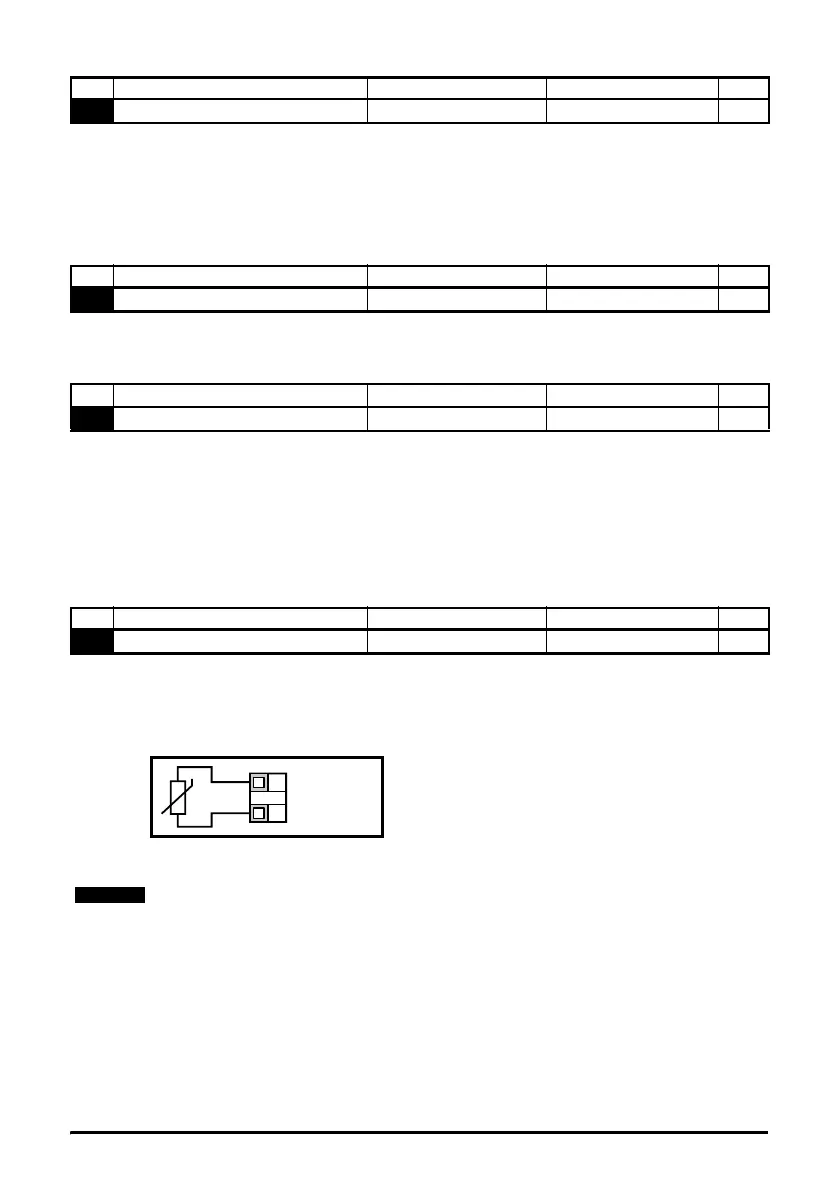
th: Motor thermistor input, connect as per diagram below
Fr: Frequency input. See Commander SK Advanced User Guide.
Fr.hr:High resolution frequency input. See Commander SK Advanced User Guide.
Figure 6-11
Trip resistance: 3kΩ
Reset resistance: 1k8
No Function Range Defaults Type
31
Stop mode select 0 to 4 1 RW
No Function Range Defaults Type
32
Dynamic V to f select OFF or On OFF RW
No Function Range Defaults Type
33
Catch a spinning motor select 0 to 3 0 RW
No Function Range Defaults Type
34
Terminal B7 mode select dig, th, Fr, Fr.hr dig RW
0V
Motor thermistor
input
T1
B7
If Pr 34 is set to th so that terminal B7 is used as a motor thermistor, the functionality of
terminal B7 as set-up with Pr 05, drive configuration, will be disabled.
When setting to th, press mode four times. Analog reference 2 will no longer be selected
as the speed reference. Analog reference 1 should be used.