14 Commander SK Getting Started Guide
www.controltechniques.com Issue Number: 9
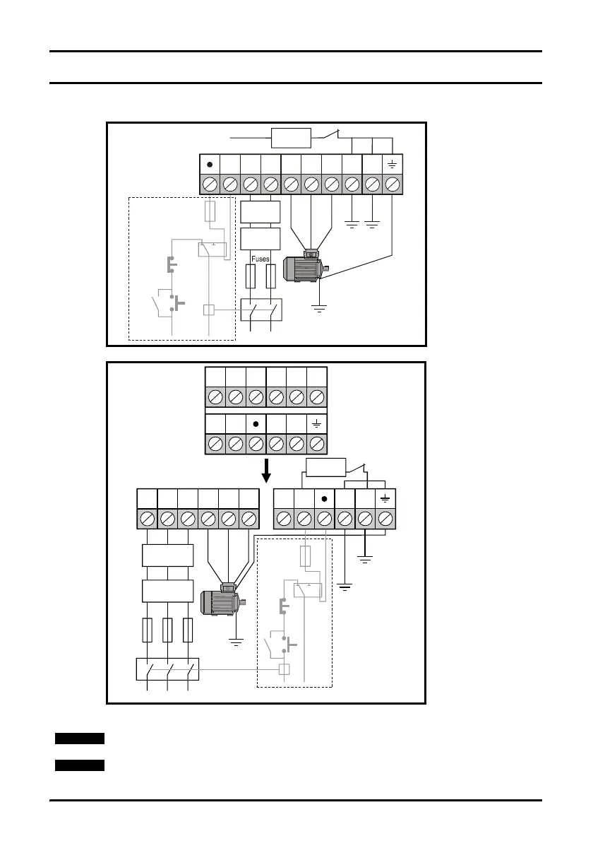
4 Electrical installation
4.1 Power terminal connections
Figure 4-1 Size A power terminal connections
Figure 4-2 Sizes B, C and D power terminal connections
*For further information, see section 4.3.1 Internal EMC filter on page 17.
Optional
ground
connection
+
L1 L2/N U V W PE
Supply
ground
Optional
line reactor
Braking
resistor
Mains supply
Optional
Thermal
protection
device
Stop
Start/
Reset
PE
Supply
ground
Internal
EMC filter
*
Optional
EMC filter
-DC
Optional ground
connection
Supply
ground
Optional
EMC filter
Optional
line reactor
Fuses
Mains supply
L3/N U V W
+
PE PE
L1 L2
_
L3/N U V WL1 L2
+
PE PE
_
Supply
ground
Internal
EMC filter
*
On the Commander SKB 110V drives, the supply should be connected to L1 and L3/N.
On the Commander SK size D, the internal EMC filter is connected to the -DC Bus.