40 Commander SK Getting Started Guide
www.controltechniques.com Issue Number: 9
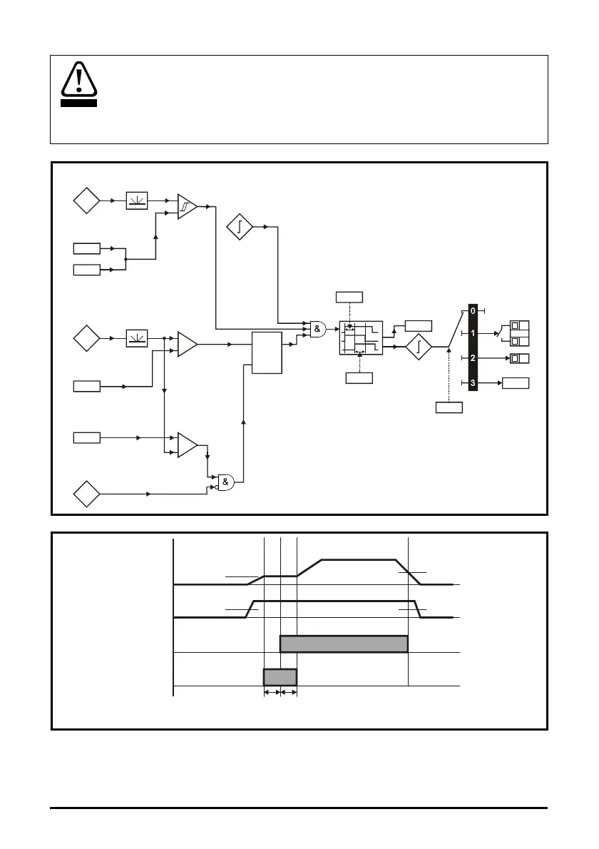
Figure 6-12 Brake function diagram
Figure 6-13 Brake sequence
The brake control functions are provided to allow well co-ordinated operation of an
external brake with the drive. While both hardware and software are designed to high
standards of quality and robustness, they are not intended for use as safety functions,
i.e. where a fault or failure would result in a risk of injury. In any application where the
incorrect operation of the brake release mechanism could result in injury, independent
protection devices of proven integrity must also be incorporated.
Current
magnitude
Brake release
current threshold
Brake apply
current threshold
46
47
+
_
Motor
frequency
Brake release
frequency
Brake apply
frequency
48
49
+
_
+
_
Reference
enabled
Latch
Drive
active
In
Out
Reset
Pre-brake
release
delay
50
Pr Brake
release frequency
48:
Pr : Brake release
current threshold
46
Ramp hold
Pr :
frequency
49
Pr :
Pre brake
release delay
50
Pr :
Post brake
release delay
51
Brake release
Output current
Output frequency
Pr :
Brake apply