Commander SK Getting Started Guide 49
Issue Number: 9 www.controltechniques.com
Safety information Rating data
Mechanical
installation
Electrical
installation
Keypad and display Parameters
Quick start
commissioning
Diagnostics
Options
UL listing
information
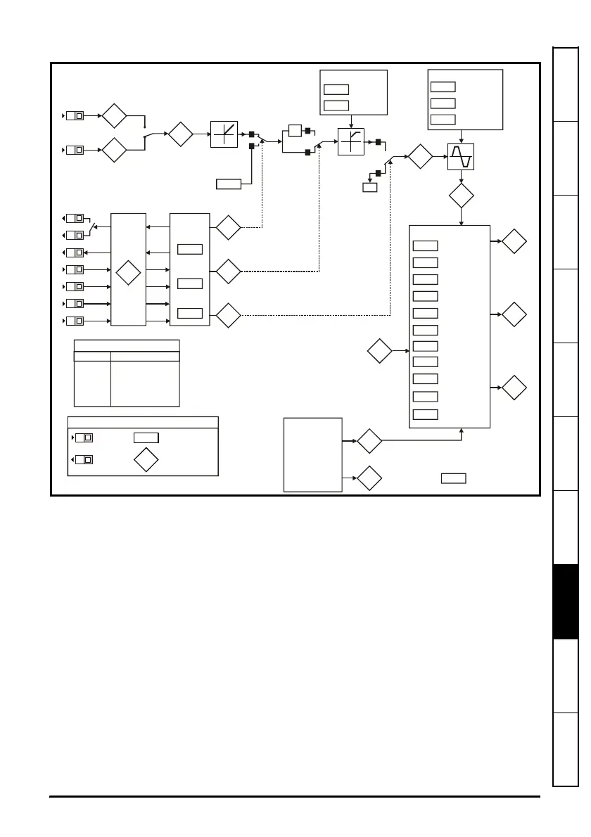
Figure 8-1 Diagnostics logic diagram
Cooling fan control (size B, C and D only)
As default, the drive’s cooling fan is controlled by the drive. The fan will remain off until
the heatsink temperature reaches 60°C or the output current rises above 75% of the
drive rating. The fan will then switch on and run at full speed for a minimum of 20s.
The cooling fan on a Commander SK size D is a dual speed fan. The drive controls the
speed at which the fan runs based on the temperature of the drives heatsink and also
the drive’s thermal model system.
For further details, see the Commander SK Advanced User Guide.
Analog inputs
94
95
81
Analog input 1 (%)
Analog input 2 (%)
Digital I/O
XX
Digital I/O
Read
word
Pr
90
Sequencer
92
93
91
Jog
selected
Reverse
selected
Reference
enabled
X-1
1
0
0
1
select
Switching
frequency
Autotune
Motor rated
frequency
No. of motor
poles
Voltage
mode select
Voltage
boost
03
Acceleration
rate
Deceleration
rate
Ramps
02
01
Minimum
speed
Maximum
speed
Speed clamps
83
Jog
reference
Digital I/O read word Pr
90
Terminal
Binary value for XX
B3 1
B4 2
B5 4
B6 8
B7 16
T6/T5 64
Frequency
reference
selected (Hz)
04
T2
T4
T6
T5
B3
B4
B5
B6
B7
XX
XX
Key
Read-write (RW)
parameter
Read-only (RO)
parameter
Input
terminals
Output
terminals
B3
B4
11
12
Start/stop
logic select
Brake
controller
enabled
31
Stop mode
select
select
30
Motor active
current
Current
measurement