ER5000 —
189
The ERTune™ Program: Power User
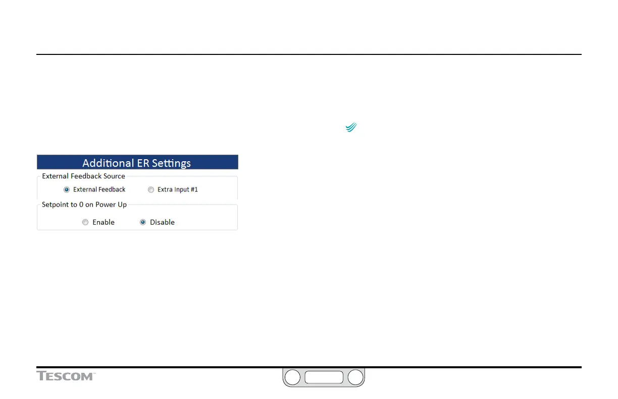
The Additional ER Settings Panel
External Feedback Source
This eld controls which feedback source displays in the Plot
Screen when you have wired the ER5000 for multiple feedback
sources. Refer to Switch Feedback Control to a Second Feedback
Source for an example of this wiring conguration.
• External Feedback is the transducer connected to the ER5000
through the orange wire (J3 Pin 3).
• Extra Input #1 is the transducer connected to the ER5000
through the brown/white wire (J4 Pin 1).
To switch the external feedback source
1. Click the radio button next the source you wish to track.
IMPORTANT
IMPORTANT
Refer to the steps To change the display of the main
(left) axis to the new range after you change the feedback source, to
be sure the ERTune™ program is tracking the correct range of values
for the new source.
Setpoint to 0 on Power Up
The ER5000 stores the last registered setpoint when it powers
down and powers up at the setpoint stored in internal memory.
Some applications may require a zero-pressure startup. This eld
allows you to set that default for the controller.
To enable Setpoint to 0 on Power Up
1. Click the Enable radio button.
 Loading...


