11
MicroVission Retrot Instructions • 35391MVRF
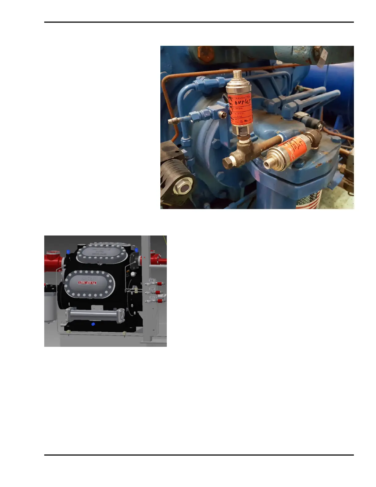
Figure 12. Tri-Micro Filter with
Pressure Transducers for Inlet
and Outlet Pressures
Step 6. Run control tubing from the valves on the Block & Bleed bracket to the compressor as shown in Figures 8, 9 & 10.
Figure 13. Location of RTDs (shown in blue)
Step 7. Install Filter Inlet and Filter outlet transducers on the Tri-Micro lter housing as shown in Figure 12.
Step 8. Install wells and mount RTDs for suction, discharge and oil temperature, see Figures 10 & 12.
Step 9. Wire the transducers and RTD’s to the MicroVission using the cords and cord grips in KT1133A4(A5). Wire
the unloader solenoid valves and crankcase heater with the cord provided in the kit. Wire tie the cords to the
compressor base as needed.
NOTE
12 and 16-cylinder compressors require two discharge
RTDs one in each discharge line.

 Loading...


