6
MicroVission Retrot Instructions • 35391MVRF
Step 4. Mount the vibration isolators on the mounting brackets and bolt the MicroVission panel to the isolators using the
hardware in KT1133A1 (see Figure 3).
Figure 3. MicroVission Panel on Support Bracket
Step 5. Remove the existing pressure transducers and RTD’s and replace RTD wells as needed. Install the ve new
transducers and three new RTD’s from instrumentation and process kits (see Table 2) and wire to the MicroVission
using the cords and cord grips in the kit. Wire the unloader solenoid valves and crankcase heater with the cord
provided in the kit. Wire tie the cords to the compressor base as needed.
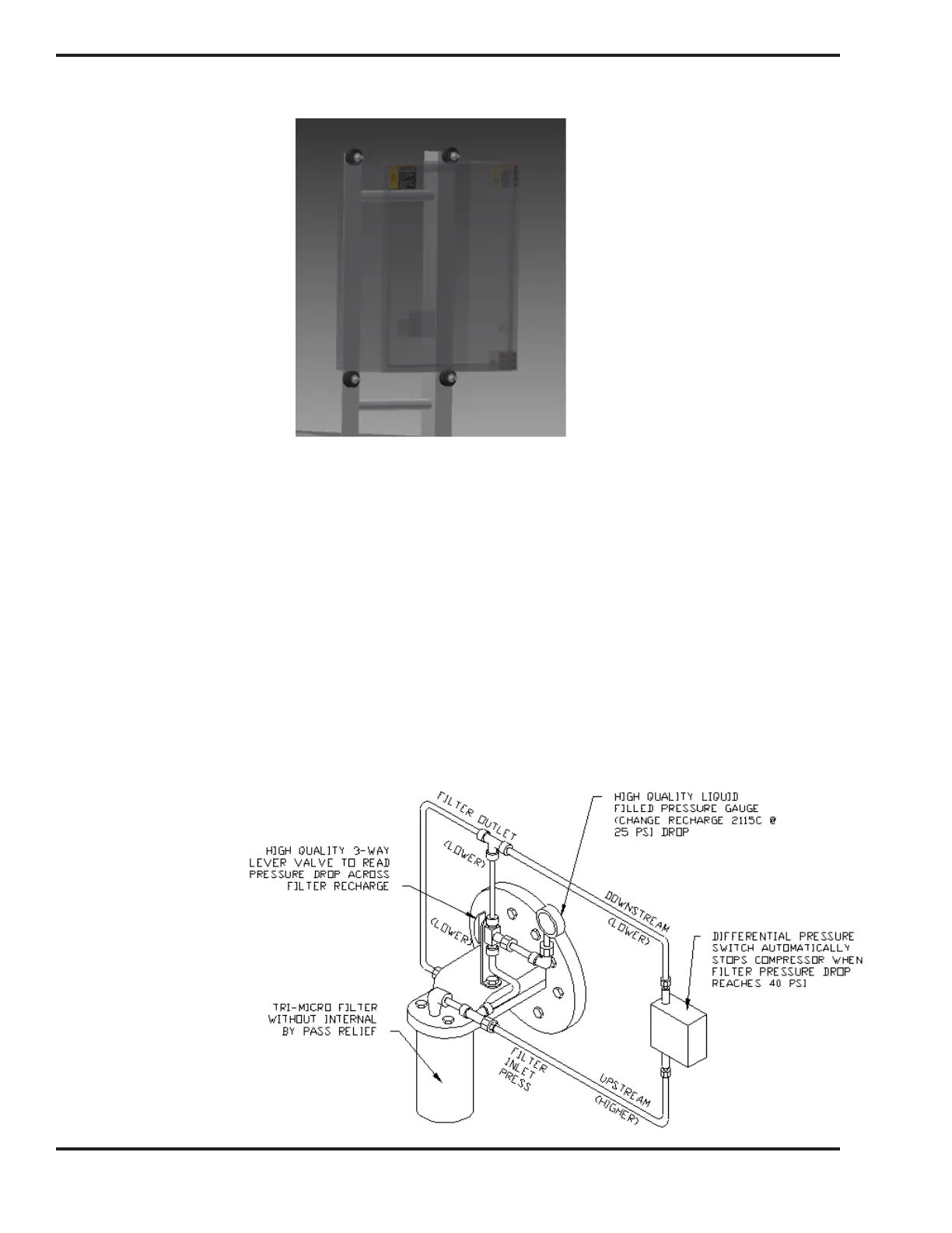
See Figure 4 for Tri-Micro conguration with pressure switch, and Figure 5 for Tri-Micro with transducers to read inlet
and outlet pressures.
Figure 4. Tri-Micro lter
with pressure switch
NOTE
If replacing a VILTech, which only uses 3 transducers, 2 ad-
ditional ones (contained in instrumentation kits KT1133A7
& KT1133A8) will be needed at the Tri-Micro lter housing
to read lter pressure drop, on the inlet & outlet pressure
points. Mount and install 1/4” ASTM A179 steel tubing
(provided by others) between pressure transducers, suc-
tion, discharge, and oil manifold connections.

 Loading...


