9
MicroVission Retrot Instructions • 35391MVRF
WARNING
When handling microcontroller, use additional
personnel or lifting device as required. Failure to
comply may result in serious injury and/or damage to
equipment.
Step 4. Mount the MicroVission bracket to the compressor frame with four (4) 3/4” bolts and hardware provided. If the
compressor base is lled with concrete the bracket can be welded to the compressor frame. Follow standard
practices for welding and fabrication procedures.
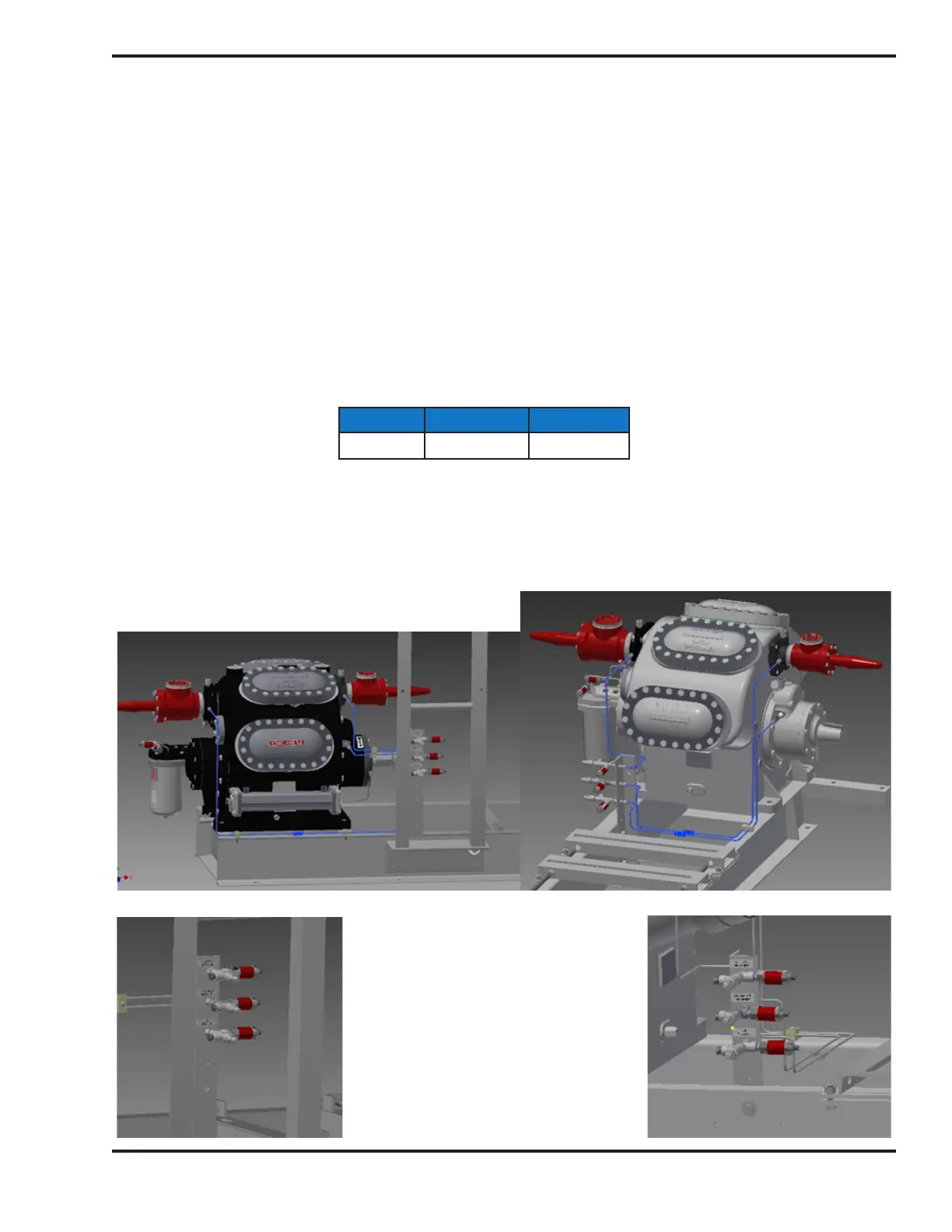
Figure 9. Tubing According to Compressor´s
Drive: Direct Drive (Left) & Belt Drive (Right)
Figure 10. Direct Drive
Transducer Mounting (left) and
Belt Drive Transducer Mounting
(right)
Step 5. Mount the Block & Bleed bracket with valves and hardware from KT1133A9(A10) and install the pressure
transducers as shown as in Figure 9 and Figure 10.
Mount and install 1/4” ASTM A179 steel tubing (provided by others) between pressure transducers, suction,
discharge, and oil manifold connections.
Verify correct transducer pressure ranges:*
Suction Discharge Oil Manifold
0-200 psia 0-414.5 psia 0-200 psia
*0-414.5 psia intermediate on integral 2-stage compressors
NOTE
If excesive vibration occurs, further support from the
controller bracket to the base may be required

 Loading...


