16
MicroVission Retrot Instructions • 35391MVRF
3.2 Order of Analog Inputs
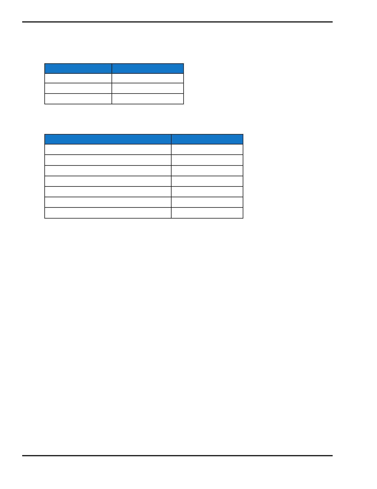
Wire black Turck cables (provided) from the RTDs to the MicroVission panel following this order:
RTD Analog Input on I/O Board
Suction Temperature AI 7
Discharge Temperature AI 8
Oil Temperature AI 9
Wire additional inputs to the MicroVission panel following this order:
Accessory Analog Input on I/O Board
Motor Current Transformer Output AI 1
Compressor Suction Pressure Transducer AI 2
Compressor Discharge Pressure Transducer AI 3
Oil Manifold Pressure Transducer AI 4
Oil Filter in Pressure Transducer AI 5
Oil Filter Out Pressure Transducer AI 6
Process Temperature Transmitter AI 10
4.0 Read MicroVission Manual
The entire manual should be reviewed before attempting to operate. Failure to follow operating instructions could result
in serious injury. Manual revision should match software version.
5.0 Power-up MicroVission and Enter Setpoints
6.0 Pressure Testing and Returning Compressor to Service
Pressure test the pressure transducer connections and install refrigerant back into the compressor and return it to ser-
vice per plant procedure.
The compressor unit must be checked for leaks after installation to ensure a tight system. For additional leak testing
information, refer to Chapter VI of ASME B31.3 Process Piping Code
Refer to your compressor manual for any additional information regarding return to service procedures.

 Loading...


