1592021021 XC1008-1011-1015D GB A5 r.1.5A 12.10.2009 XC1008-1011-1015D 47/66
9. ANALOG OUTPUTS FOR INVERTER
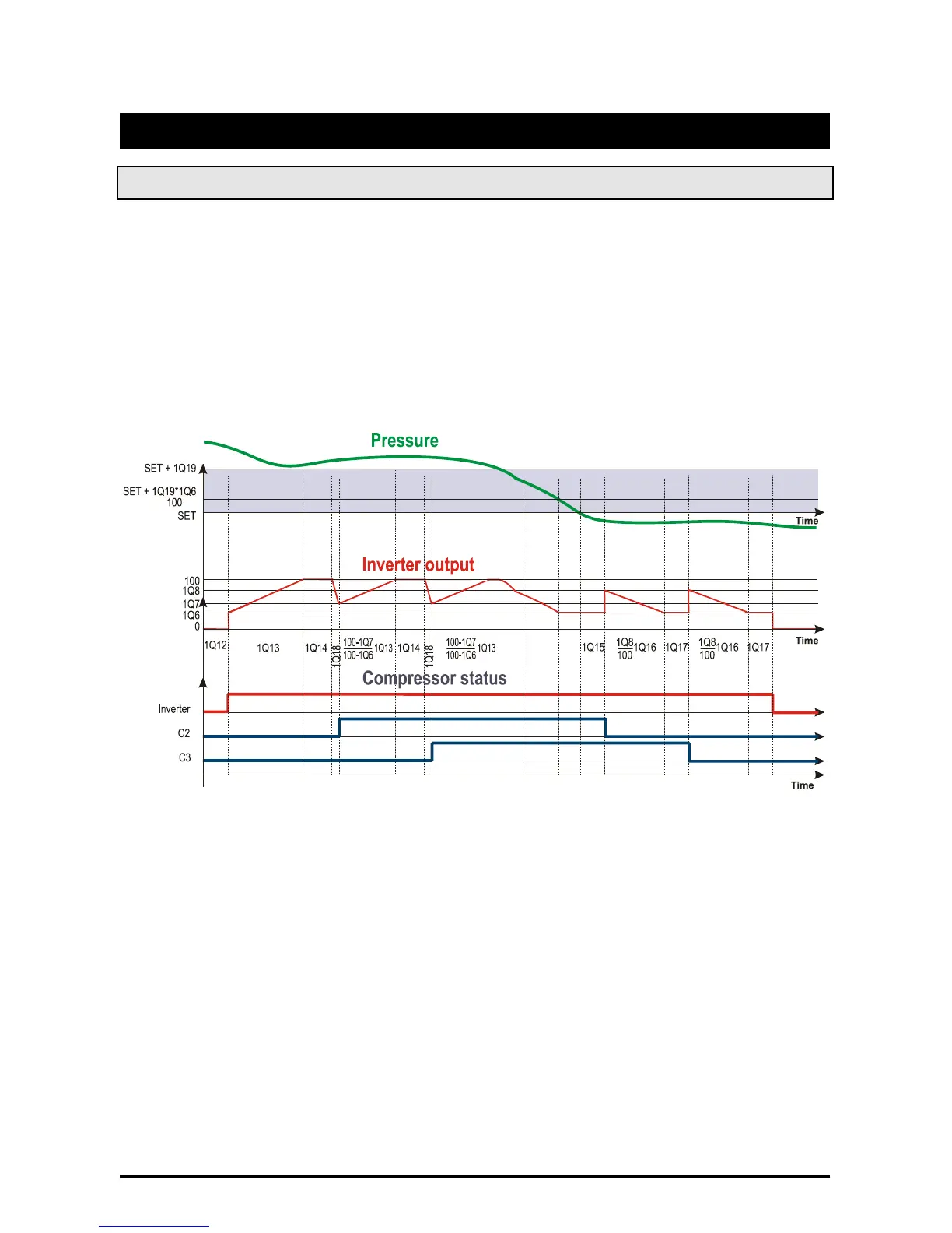
9.1 Compressor management
The analog outputs can be used in a rack with frequency compressor, driven by an inverter.
The regulation of the compressors in this case is changed as described in the following graph:
The following examples shows the behaviour of the analog output with proportional regulation.
ES.
3 compressors, 1 frequency compressor
C1 = FRQ1 C37 = db 1Q8 < 100
C2 = CPR1 1Q2 = CPR
C3 = CPR1 1Q7 < 100
where
1Q6 Minimum value for analog out.1
0 ÷ 100 %
1Q7 Analog output1 value after compressor on
1Q6 ÷ 100 %
1Q8 Analog output1 value after compressor off
1Q6 ÷ 100 %
1Q12 Regulation delay after entering the regulation band
0 ÷ 255 (sec)
1Q13 Analog output 1 rise time
band and a load is switched on.
0 ÷ 255 (sec)
1Q14 Analog output 1 permanency at 100% before load activation
0 ÷ 255 (sec)
1Q15 Delay between pressure (temperature) goes down the set point and start of analog
output 1 decreasing
0 ÷ 255 (sec)
1Q16 Analog output 1 decreasing time from 100% to the 1Q6 value
0 ÷ 255 (sec)
1Q17 Analog output1 permanency at 1Q6 before a load is switched off
0 ÷ 255 (sec)
1Q18 Analog output1 decreasing time, from 100% to 1Q7 when a load is switched on
0 ÷ 255 (sec)