1592021021 XC1008-1011-1015D GB A5 r.1.5A 12.10.2009 XC1008-1011-1015D 50/66
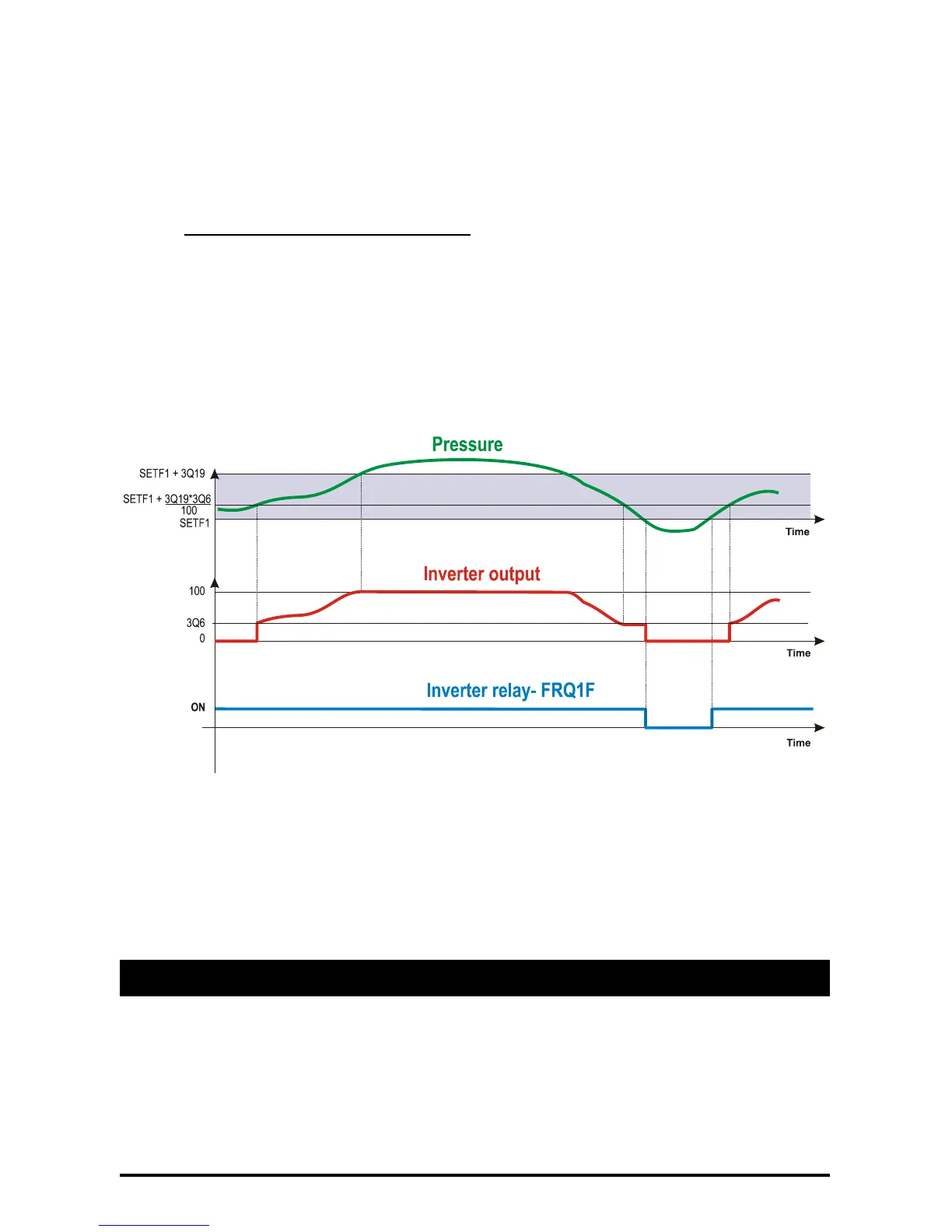
Below the SETF the output is OFF, above the SETF the output works at 100%.
If the delivery pressure/temperature is higher than the SETF1(2) value, the relay set as inverter is
ON; if the delivery pressure is lower than the SETF1(2) value the relay is OFF.
9.3.1 Use of fans thermal protection
With this configuration it’s possible to use XC1000D digital inputs to monitor the fans functioning.
It’s necessary to set as much relay as used fans. Connect the thermal protection of every fans to its
digital input of the relay set as fan.
DON’T USE relays set as fans.
ES.: 4 fans, driven by one inverter.
C1 = FRQ1F C2 = FAN1 C3 = FAN1 C4 = FAN1 C5 = FAN1
3Q2 = INVF1 3Q3 = PBC3 3Q19 = Regulation band width
3Q6= min. value analog output
With this configuration, connect the thermal protection of:
- fan 1 to terminals: 5-6 (i.d. 2)
- fan 2 to terminals: 7-8 (i.d. 3)
- fan 3 to terminals: 9-10 (i.d. 4)
- fan 4 to terminals: 11-12 (i.d. 5)
In this way any fans problem is sent to the controller (even if doesn’t affect the regulation)
10. Alarm list
Usually alarm conditions are signalled by means of:
1. Activation of alarm relays
2. Buzzer activation
3. Message on proper display
4. Log of alarms, hour, data and duration