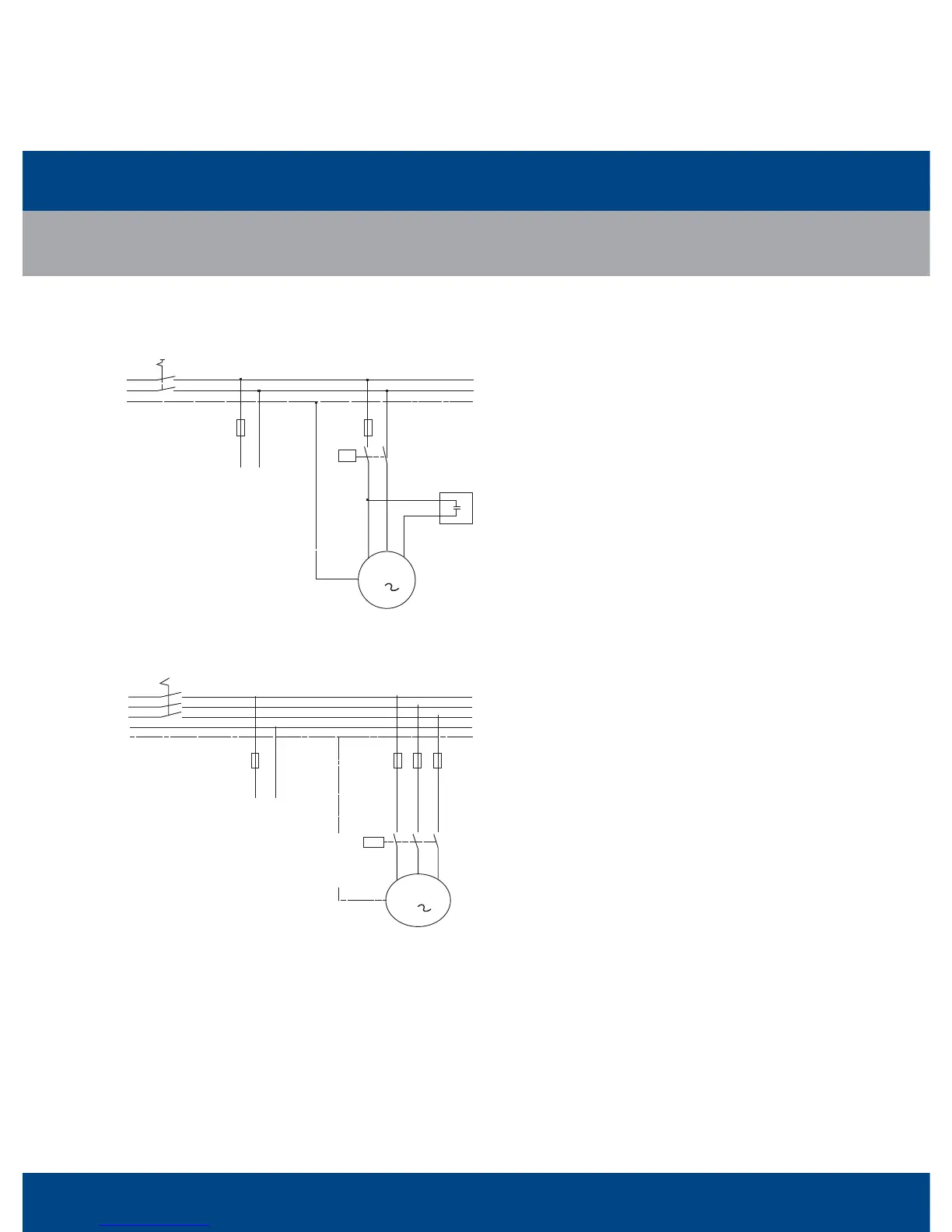
66
C2
L1
N
PE
Q1
L1
K1
N
F1
F6
R
C
S
M
1
To Control Circuit
L1
L2
L3
N
PE
L1
F1
F6...8
L1
K1
L2
L3
N
Q1
M
3
To Control Circuit
Single Phase Circuit (ZB15-ZB29)
Electrical Schematics
L1/N/PE: Single Phase Lines (line/neutral/ground)
Q1: Manual Switch
F1/F6: Fuse
K1: Compressor Contactor
C2: Run Capacitor
M: Compressor Motor
R/C/S: Compressor Terminal
3 Phase (ZB15-ZB114)
(with Motor Protection Code “F”)
Electrical Schematics
L1/L2/L3/N/PE: 3 Phase Lines (line/neutral/ground)
Q1: Manual Switch
F1/F6..8: Fuse
K1: Compressor Contactor
M: Compressor Motor
L1/L2/L3: Compressor Terminal
ZB Series
Electrical Wiring Diagram
ZB15
~
ZB114
 Loading...