Comfort where it counts 10 P/N 240008111, Rev. G [06/18/10]
Electrical Wiring (continued)
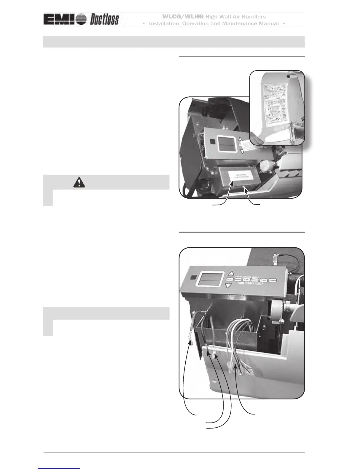
Wiring diagram locationFigure 9
Control box
Remove screw
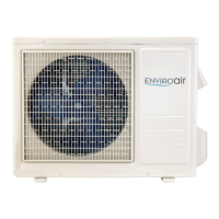
Wiring connectionsFigure 10
Low Voltage
Connections
Ground
L1
L2
Connect wiring
To access High and Low volt wiring re-1.
move the screw on the front of the control
box. (Figure 9, pg. 10)
High voltage electrical wiring
Refer to the wiring diagram to connect the 1.
power wire to Black L1 and the other wire
to Red or White (115V) L2 at the power
connector location. (Figure 10, pg. 10)
Connect the ground wire to the ground 2.
lug or lead at the same location in the
control box.
WARNING
Terminate ALL unused wires with a wire
nut or crimp connector.
Low voltage electrical wiring
(for unit-mounted controls)
The 24V control transformer is located 1.
in the air handler. is provides low Volt
control power to both the air handler
and condenser. Depending on the mod-
els selected, the low volt interconnect
control wiring may be eected. (Figure
10, pg. 10)
NOTICE
All low voltage interconnect wiring must
be at least 18 AWG.


 To Next Page