P/N 240008111, Rev. G [06/18/10] 9
Electrical Wiring
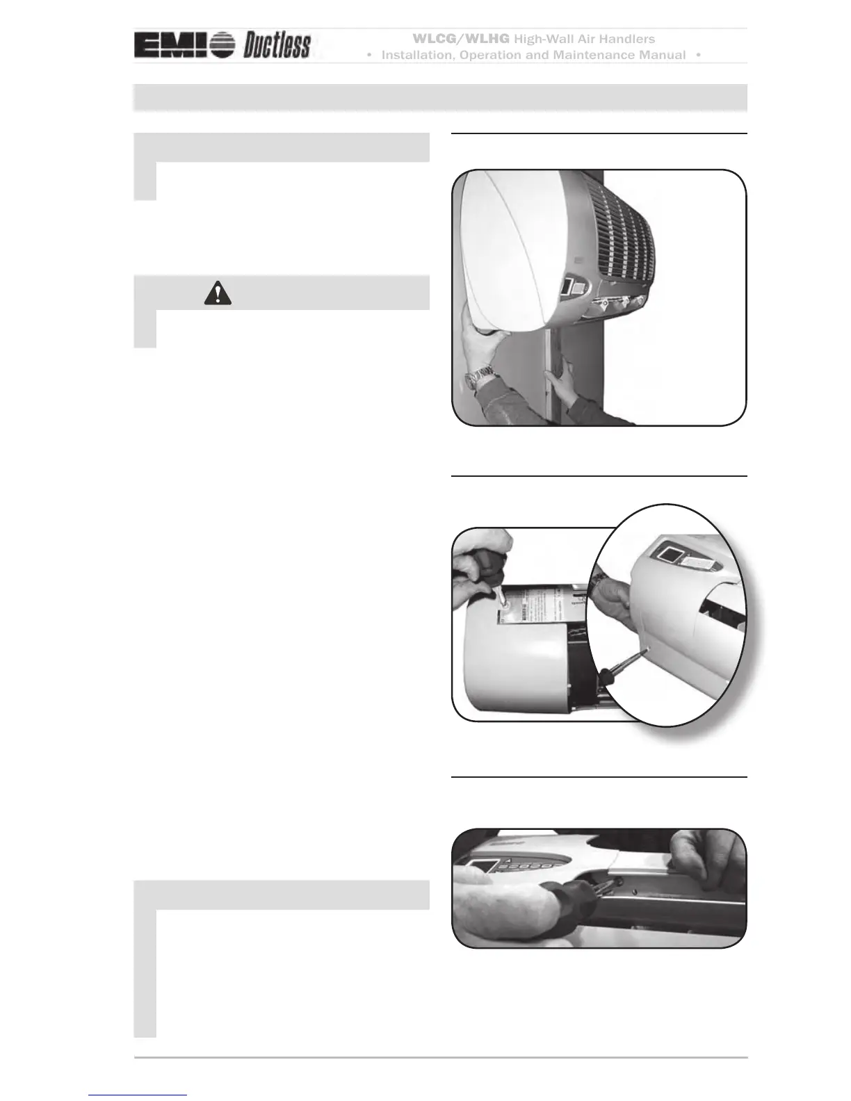
Before removing end capFigure 6
Helpful Tip:
Prior to remov-
ing the end
cap and
bottom
use a
small
board to
prop the unit
away from the wall.
Removing end cap
Figure 7
Rotate louver down to expose Figure 8
screw
NOTICE
All electrical wiring must be run accord-
ing to NEC and local codes.
Site preparation for wiring
WARNING
Electrical shock hazard Make sure the
power is o before proceeding.
Check the unit rating plate for minimum 1.
circuit ampacity and breaker or time delay
fuse size. Use only HACR type breakers.
Select the proper wire for the ampacity
rating.
Each unit must have a separate branch 2.
circuit protected by a time delay fuse or
breaker. Refer to the unit rating plate for
the proper wire and breaker or time delay
fuse size.
Inspect the existing wiring for any defects 3.
such as cut or frayed wires. Replace if any
such wiring if found.
e le end cap of the unit needs to be 4.
removed to access wiring diagram and
electrical wiring. is requires removal
of three screws (Figure 6, Page 9 and
Figure 7, Page 9).
Rotate louver down to expose the third 5.
screw (Figure 8, Page 9).
Once the screws are removed, slide the 6.
le end cap o to expose control box and
locate the wiring diagram on the inside
of the end cap.
NOTICE
On units rated 208/230V, the primary
side of the transformer is factory wired
for 230V. For a 208V power supply,
the transformer tap must be changed
from orange to red. Refer to the wiring
diagram located on the inside of the le
end cap of the unit.