Comfort where it counts 36 P/N 240008111, Rev. G [06/18/10]
Troubleshooting
WARNING
Service should be performed by a quali-
fied service agency
and an annual system
check is recommended.
Electrical shock hazard Before re-
moving access panels or control covers to
expose moving parts of non-insulated live
electrical components for service, discon-
nect all high volt power supplies to both
the indoor unit and outdoor unit. Failure
to do so could result in physical injury and/
or electrical shock.
Wiring diagram
When trouble-shooting the indoor unit,
please refer to the wiring diagram that is sup-
plied with the equipment.
The wiring diagram is located on the •
inside surface of the le end cap.
Access the wiring diagram and wiring fol-•
lowing the procedure on page 9.
If you are unable to locate the wiring •
diagram, please call the factory technical
service line at (800) 228-9364, and one
can be faxed, mailed or e-mailed. Please
have the full model and serial number
available prior to calling.
Wiring requirements
EMI Series air handlers are designed to oper-
ate with EMI Series condensers.
e air handler (indoor unit) and con-•
denser (outdoor unit) must be indepen-
dently connected to the electrical service
panel and protected by separate time
delay fuse or HACR breakers. (See the
unit name plate for the correct breaker
type and size).
e indoor and outdoor units are also •
connected to each other via a 24V inter-
connect wiring.
A transformer provides the low volt power •
source for the controls. e number of low
volt interconnect conductors will be two
to six depending on heating options and
or thermostat selection.
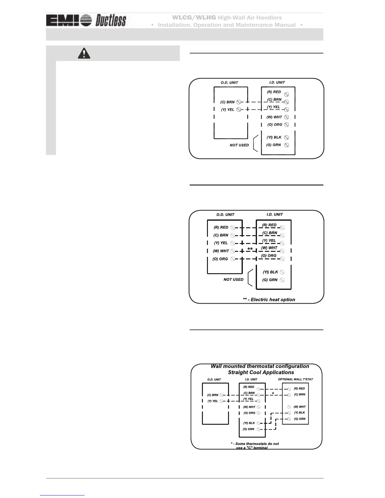
Wiring connections — straight Figure 36
cool applications
Wiring connections — heat Figure 37
pump applications
Wiring connections — straight Figure 38
cool applications with wall
thermostat
 Loading...


