P/N 240008111, Rev. G [06/18/10] 37
Troubleshooting (continued)
Interconnect wire should be at least •
18 AWG.
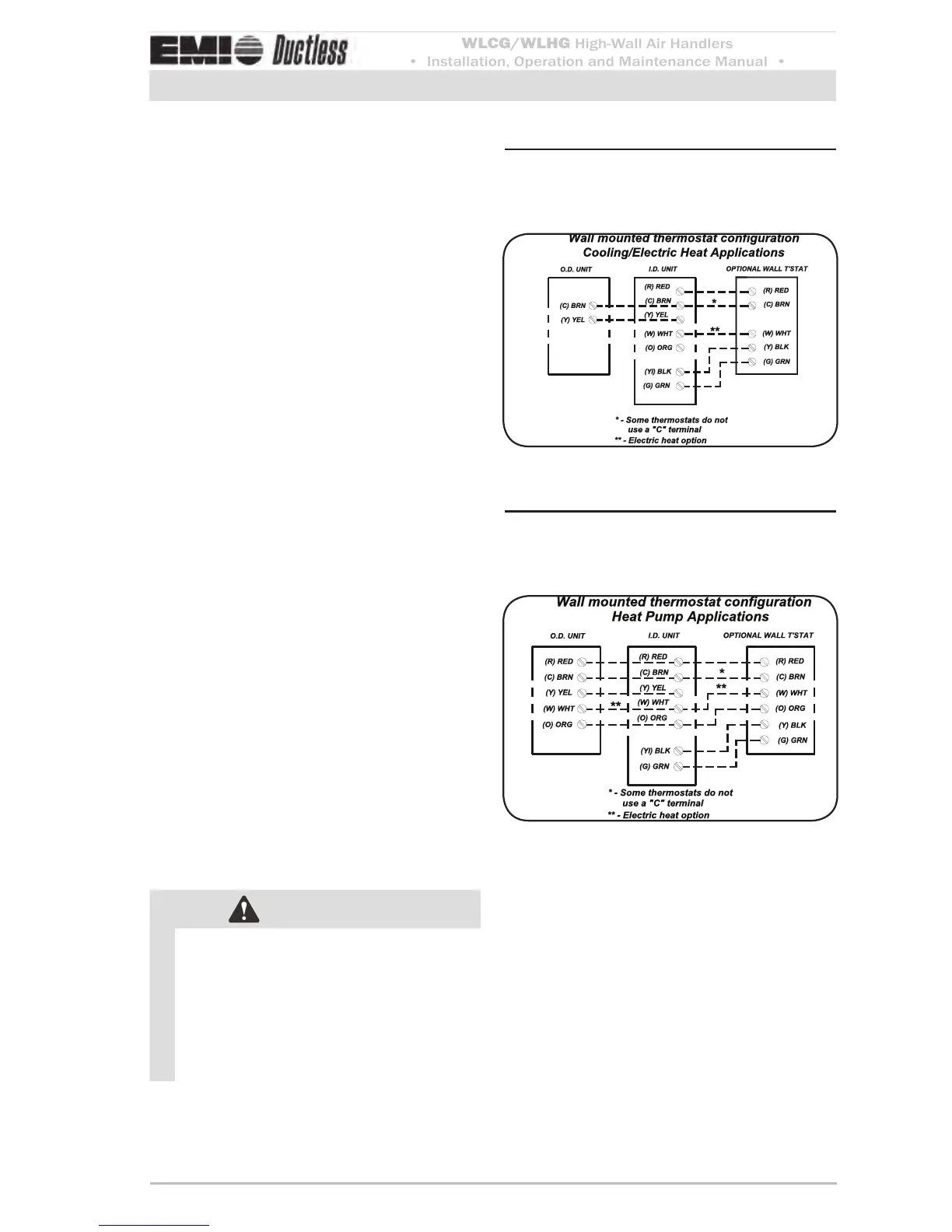
Refer to the unit wiring diagram for the •
interconnect diagram that matches your
system.
Power supply check
When troubleshooting any EMI product, it
is important to rst check the rating plate for
proper eld voltage and breaker size.
en use a voltmeter to check the incoming
power supply to verify that it agrees with the
rating plate.
e incoming power must not exceed the •
nameplate voltage.
e incoming power must not be below •
the minimum voltage stated on the rating
plate (197V for units rated 208/230V and
104V for units rated 115V).
Also verify low voltage power place a volt-
meter across low volt terminals R and C at the
indoor unit. e voltage should be 24V.
Test mode
Test mode is available for unit-mounted con-
trol conguration only. Use of test mode can
aid in the functional check of the unit. It can
also be a helpful tool when troubleshooting to
solve a problem. While in test mode all timers
are shortened. See (Figure 29, Page 23) for
access information.
WARNING
While in test mode, all cycle times are re-
duced by 1/4 of original time for testing.
Avoid short cycling the compressor. Aer
system checks are complete, the control
must be returned to normal operation.
DO NOT LEAVE THE SYSTEM IN TEST
MODE
.
Wiring connections — cooling/Figure 39
electric heat applications with
wall thermostat
Wiring connections — heat Figure 40
pump applications with wall
thermostat
 Loading...


