Comfort where it counts 12 P/N 240008111, Rev. G [06/18/10]
Electrical Wiring (continued)
Wall thermostat controls
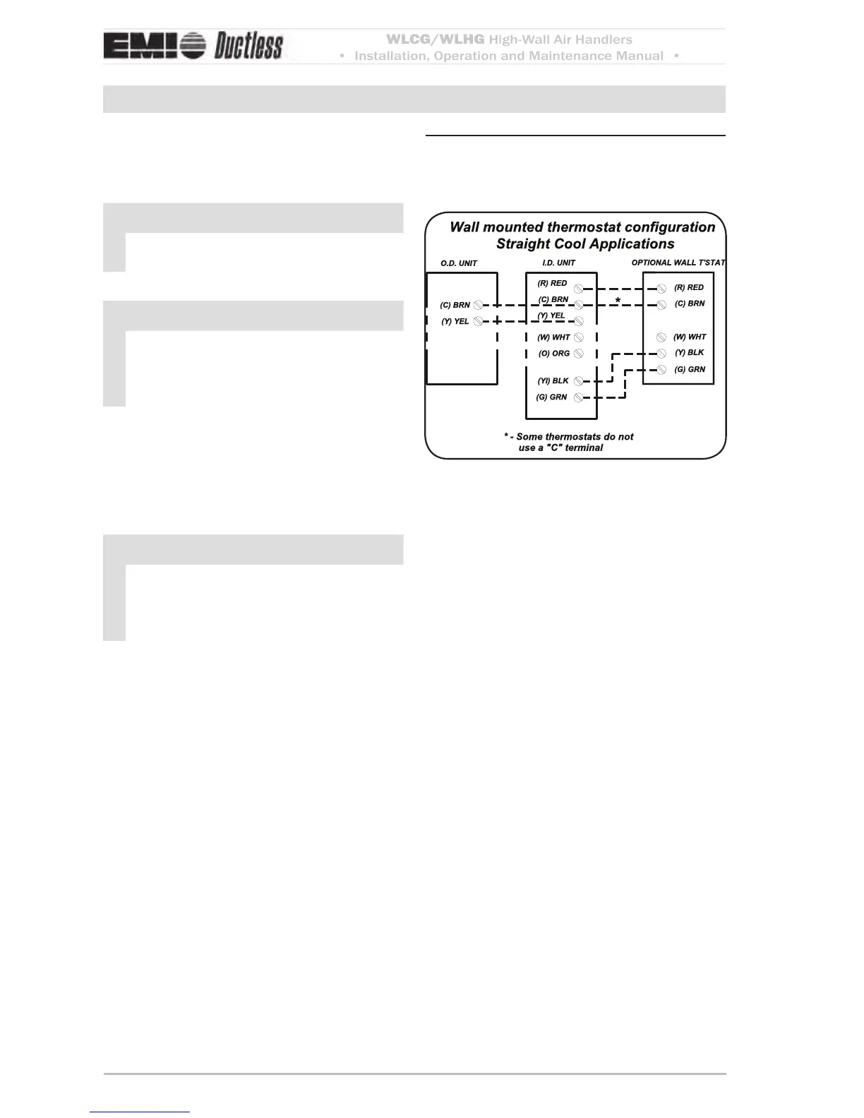
For remote wall mounted thermostat layout see -
(Figure 13, pg. 12)
NOTICE
All low voltage interconnect wiring must
be at least 18 AWG.
NOTICE
Unit mount control — If the control
is configured for unit mount control
DO NOT connect a wall thermostat to
the unit.
The 24V control transformer is located in the
air handler unit
. is provides low volt control
power to both the air handler and condenser.
Depending on the models selected, the inter-
connect control wiring may be eected.
NOTICE
For wall thermostat mode, the key pad
will have limited operation (see Se-
quence of Operation Wall-mounted
thermostat, page 29).
Choosing a remote wall-mounted
thermostat
See page 29 for wall thermostat selection
information.
Depending on the thermostat required or se-
lected, air handlers may utilize four to six low
volt interconnecting wires between the indoor
unit, thermostat and outdoor unit.
Some thermostats do not require the use of
the “C” (brown) connection. In this case,
ensure that any unused wires are insulated
with a wire nut to prevent them from making
contact with the junction box or other metal
surfaces.
Wall-mounted thermostat Figure 13
configuration —
cooling only


 To Next Page