P/N 240008111, Rev. G [06/18/10] 15
Refrigerant Piping (continued)
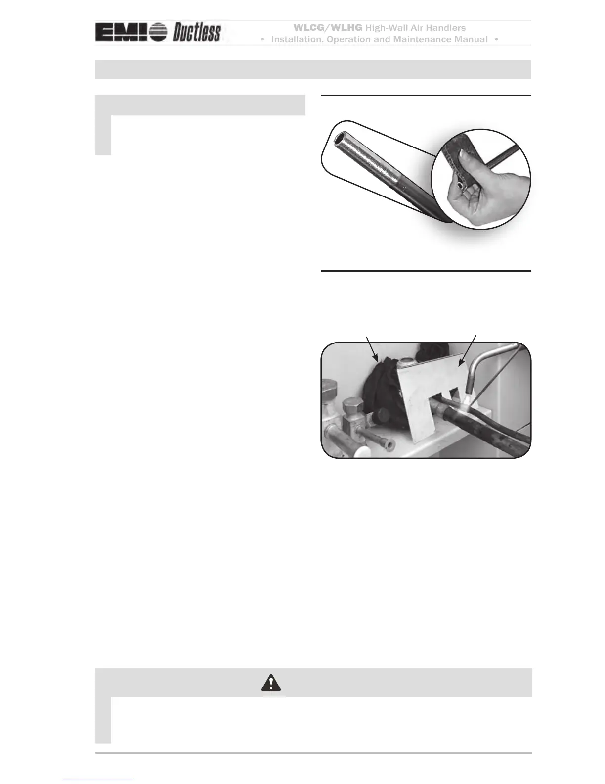
Clean ends of tubingFigure 18
Place wet rag “heat shield” over Figure 19
valves plus a sheet metal shield
to protect paint
Wet rag heat sink
Shield
NOTICE
e WLCG/WLHG is equipped with
a Flo Rater piston expansion device or
TXV. Connections are sweat type.
Line sizing
Size lines per (Table 7, Page 43).1.
e suction line size must match the con-2.
denser service valve connection.
When matching the WLHG24 with a.
an 18,000-Btuh condenser, you must
use a 5/8-inch suction line, with a
reducer installed as shown in (Fig-
ure 17, Page 14).
Refrigerant piping
Clean the ends of tubing and insert into 1.
ings (Figure 18 page 15).
Before brazing (Figure 19 page 15):2.
Protect valves by wrapping with a wet a.
rag “heat sink” before brazing.
Use a shield to protect the paint as b.
shown. (e shield can be made from
scrap metal.)
Braze tubing into ings, using a continu-3.
ous nitrogen purge.
e suction line must be insulated the 4.
entire length with closed cell, foam tube
insulation.
Do not insulate the liquid line.5.
Connect the outdoor unit according to 6.
the instructions supplied with unit.
All horizontal piping runs must be level 7.
and without dips to trap the oil.
CAUTION
Pressure test all eld installed piping with nitrogen. Using a suitable vacuum pump,
evacuate the tubing and indoor unit to 500 microns or less, with service valves remaining
front seated (closed).


 To Next Page