59
1. DESCRIZIONE DEI COMPONENTI
GBGB
Vite meccanica
Vite autofilettante
Vite autofilettante
70 mm
6 mm
655 mm
990 mm
500mm
245 mm
65 mm
125 mm 100 mm
65 mm
530 mm
45 mm
70 mm
35 mm
(Fig. A)
6. INSTALLATION OF THE INDOOR UNIT
- After the installation on the ceiling, adjust the unit on the right position
and control it is at the level.
Nota:
The indoor unit includes a condensation drain pump and one float switch,
therefore you have to assure not to tilt it. If unit is tilted toward the
opposite side of the condensation drain piping, floating switch does not
work properly and you may have some losses.
- Once direction has been chosen, drill a hole of 70mm diameter on the
wall so that pipe directed towards the outside is inclined downward
to ease the water discharge.
Indoor Unit Outdoor Unit
Wall
Make sure the unit is perfectly level.
Level
- Attach the condensate drain connection to the unit using a hose
clamp. Insert the drain connection inside the condensate drain hole.
- Tighten the clamp.
- Wrap an insulating sheet around the hose clamp to seal it to the con-
densate drain fitting. Insulate the condensate drain pipes inside the
room.
The condensate pump and its float switches are inside the unit.
If the unit is not perfectly level, the function of the float switch could be
done incorrectly and could cause leakage of water.
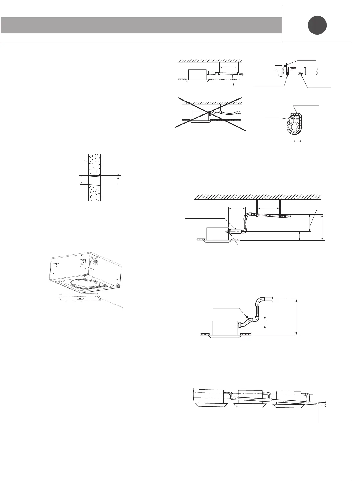
- The maximum slope of the fitting condensate drain must be equal to
75mm, so that the condensate drain hole should not endure excessive
force.
- If you have to dispose several condensation discharge piping for
more than one indoor unit, place the common pipe about 100mm
below the condensation drain hole of every unit.
- The drain head can be raised up to 280mm maximum over the exit
from the indoor unit
- Pipe should create a right angle if compared to the unit, at a distance
of 300mm from it.
6.3 Installation of the water draining pipe
Diameter of condensation drain pipe has to be the same or bigger than
the one of the indoor unit piping.
Condensation drain piping should be short and installed with a downward
slope of at least 1/100. Avoid to route piping through an higher point and
to create some siphons.
If a slope to the condensation drain pipe cannot be given, it is necessary
to install the supporting brackets.
Keep a distance of 1-1,5m between the support brackets to ensure a
straight pipe.
1-1.5m
<280mm
<500mm
<500mm
<75mm
220mm
<300mm
1-1.5m
>100mm
CORRECT
sope > 1/100
1-1.5m
<280mm
<500mm
<500mm
<75mm
220mm
<300mm
1-1.5m
>100mm
FALSE
1-1.5m
<280mm
<500mm
<500mm
<75mm
220mm
<300mm
1-1.5m
>100mm
Hose clamp
Adhesive tape
Condensation discharge
fitting
1-1.5m
<280mm
<500mm
<500mm
<75mm
220mm
<300mm
1-1.5m
>100mm
Hose clamp
Insulating sheet
< 4 mm
<280mm
<500mm
220mm
<300mm
1-1.5m
Fitting
Condensation drain
Ring
Pipe raising
Supporting bracket
Fig. C
<500mm
<75mm
Fitting
condensate drain
1-1.5m
<280mm
<500mm
<500mm
<75mm
220mm
<300mm
1-1.5m
>100mm
Slope > 1/100
Connect the condensation drain
pipes with a T joint
 Loading...