EL – Owner’s Manual – Rev.00 – September 2021 24
potential over-voltages generated by lightning strikes, as well as an appropriately sized differential
breaker for the installation.
In the DC version, the chassis needs to be grounded separately to prevent contact with dangerous
voltage and to allow the correct functioning of the device. The grounding system must comply with
local and national regulations. Remove the screw and the washer from the labelled spot on the back
side of the electrolyser and use them to connect the ground cable.
Grounding symbol on device
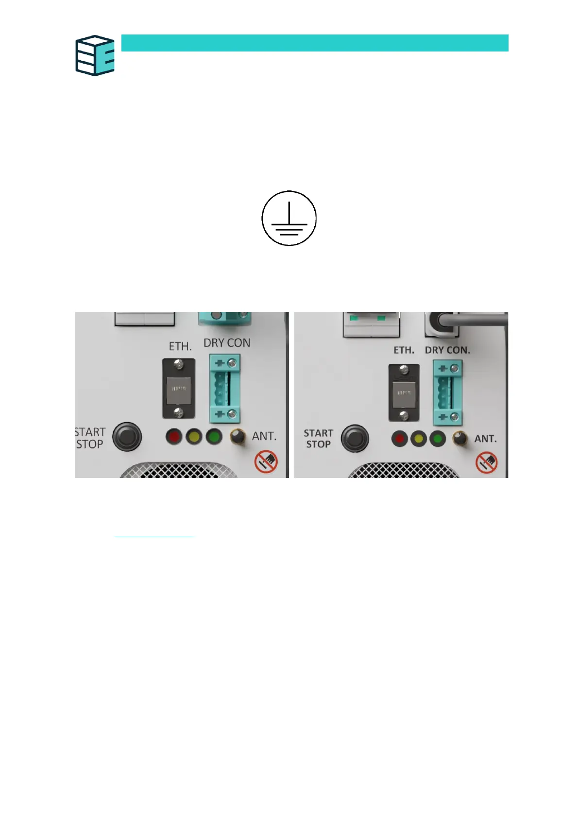
Ethernet Port (ETH.)
The front panel features an ethernet port.
This Ethernet port allows Modbus access. The Modbus command interface table can be accessed
online via Enapter handbook.
Dry Contact Connection Guide (Optional) (DRY CON.)
The device can be integrated into existing dry contact chains. If no dry con chain needs to be
integrated, please jump to the section below.
Connect the male connector to the female port on the device, labelled “DRY CON”. The dry contacts
are normally-closed type.
The pins are, from top to bottom, S2, COM2, S1, COM1. This allows the device to not only receive a
dry contact signal but also to pass it on to the next Enapter device, allowing the operator to daisy chain
as many Enapter devices as wanted to a common safety signal.