EL – Owner’s Manual – Rev.00 – September 2021 12
Safety areas around the purge and vent outlet
Generally, there are two options. The extents of this safety area depend on different parameters, for
example, the diameter and the length of piping leading to the safe area, the vent spout design, exit
velocity and wind conditions.
Preferably, the operator:
1. calculates the measurements of the safety area based on the provided data for each specific
output and applies industrial standards such as the following to their system design, safety
concept and site documentation.
• EIGA Doc 211/17: Hydrogen Vent Systems for Customer Applications
• CGA G5.5: Hydrogen Vent Systems
• ISO/TR 15916:2015: Basic considerations for the safety of hydrogen systems
2. Or follows the recommendations of Enapter for systems consisting of up to ten electrolysers
and two dryers. The safety area is cylindrical and has a height of 10 meters and a radius of 5
meters. Note that depending on the design of the purge piping and exit velocity, this area also
extends in the direction of the ground by at least 1 meter.
3. Never place the vent outlet near the purge outlet to minimise the risk of explosion. Leave at
least 3 meters of space between the gas outlets.
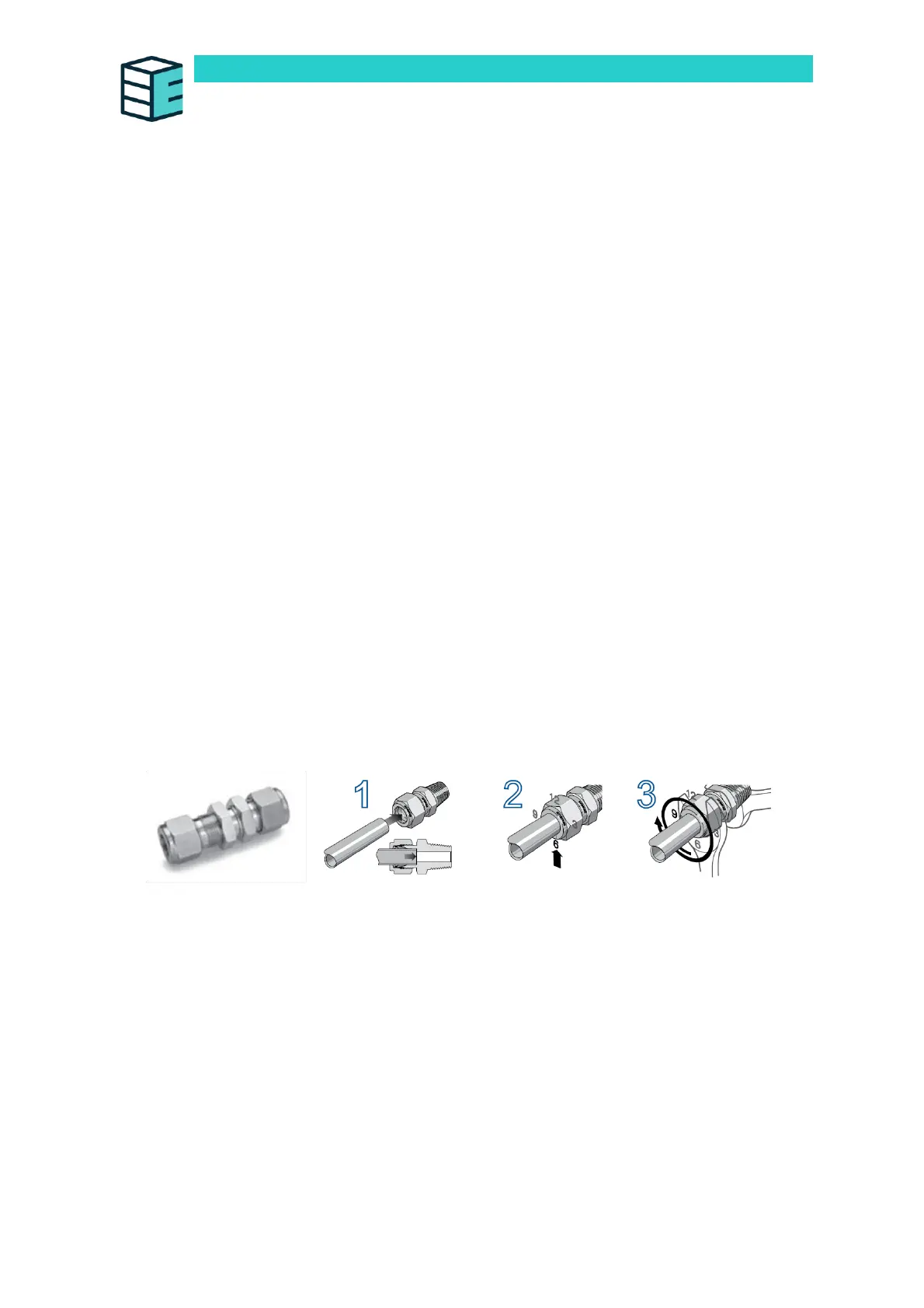
INSTRUCTIONS FOR CONNECTING STAINLESS STEEL TUBES
All pressurised hydrogen gas connections are Swagelok tube fittings for ¼” outside diameter (OD)
tubes. The outlets to be connected according to these instructions are labelled “H
2
Out” and “H
2
Purge” on the front panel of the device.
Follow the below instructions carefully – please refer to the Swagelok manufacturers installation guide
for any further details: An Installer's Pocket Guide for Swagelok® Tube Fittings (MS-13-151).
1. Fully insert a ¼” stainless steel tube into the bulkhead union, with the nut and ferrule in place
on the fitting.
2. Rotate the nut finger-tight, then mark the 6 o’clock position on the nut.
3. Hold the fitting body steady on the device using the 5/8” open key wrench.
4. While holding the fitting body steady, tighten the nut one and one quarter turns to the
9 o’clock position with the 9/16” open key wrench.
5. To ensure a leak-proof connection is made, another quarter-turn of the nut (to the 12 o’clock
position) is recommended.
Always check each connection for leaks! For more information, please refer to Appendix I below.