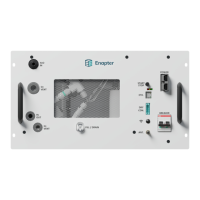
4.2.2 MATERIAL
The amount of each material depends on the individual setup
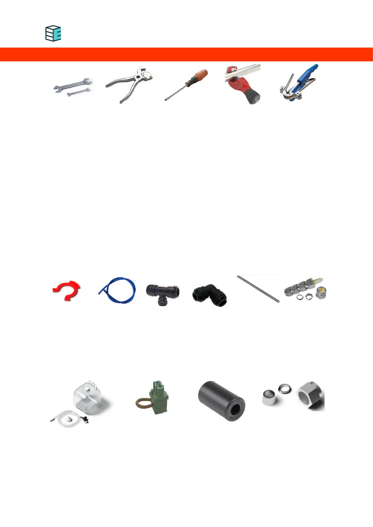
L-pieces, I-pieces and T-pieces for the LDPE and stainless steel pipes
H
2
O IN:
o Push-fit locking clips for 10 mm pipes (to fix the pipes within the connectors)
o 10 mm diameter LDPE tubing (ensure the tubing is pressure-resistant to at least 4 bar!)
H
2
OUT/VENT:
o Swagelok SS-6M0-1-4RS, Swagelok SS-400-1-4RS with Swagelok -4-RS-2V
o Stainless steel pipe AISI 316 - ASTM A269 - ¼” outside diameter x 0.035” wall thickness
or equivalent material in terms of resistance to corrosion, fire conditions and the required
pressures of at least 40 barg
O
2
VENT:
o Swagelok SS-600-1-6RS, Swagelok SS-10M0-1-6RS
o Stainless steel pipe AISI 316 - ASTM A269 - ⅜” outside diameter x 0.035” wall thickness
or equivalent material in terms of resistance to corrosion and fire conditions
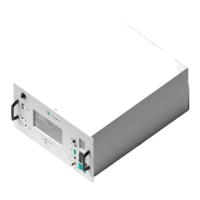
4.2.3 ACCESSORIES (INCLUDED IN THE BOX)
Electrolyte filling bag with pipe and connectors (labelled)
Dry contact jumpers
Ferrite cylinder for power input cable
Swagelok Nut and Ferrule set
4.3 IMPLEMENTING SYSTEM SAFETY
Each connection to and from the device must be inspected and tested. Additional system engineering
might be required to ensure safe operation.