Always follow best practices, apply your local codes of regulation (if applicable), and follow industry
standards for the implementation of safety systems to manage the risks of running electrolysers and
storing hydrogen.
Gas containing pipes must be properly connected to the specific ports, tested by the operator, and
directed to separate safe areas. If this is not possible, the operator must find another safe solution,
such as using a flare stack, burn box, or forced dilution. When forced dilution is utilised, all components
used in this process must not be able to ignite the hazardous substances.
Caution! The device produces explosive and highly volatile gases!
It is the operator’s responsibility to ensure good engineering practices are applied to
the hazardous substances which are released during the operation of the device!
The operator must ensure that the outlet satisfies all relevant local rules and regulation,
in terms of the safe dispersion of the vented gas, noise emission, risk assessments,
maintenance, a satisfactory safety concept being utilised, and all other relevant areas.
It is the operator’s responsibility to regularly check and maintain all pipes.
4.3.1.1 SAFETY AREAS AROUND THE O
2
VENT AND H
2
VENT OUTLET
Generally, there are two options. The extents of this safety area depend on different parameters, for
example, the diameter and the length of piping leading to the safe area, the vent spout design, exit
velocity and wind conditions.
Preferably, the operator:
1. calculates the measurements of the safety area based on the provided data for each specific output
and applies industrial standards such as the following to their system design, safety concept and
site documentation.
EIGA Doc 211/17: Hydrogen Vent Systems for Customer Applications
CGA G5.5: Hydrogen Vent Systems
EIGA Doc 154/16: Safe location of oxygen and inert gas vents
ISO/TR 15916:2015: Basic considerations for the safety of hydrogen systems
2. Or follows the recommendations of Enapter for systems consisting of up to ten electrolysers and
two dryers. The safety area is cylindrical and has a height of 10 meters and a radius of 5 meters.
Note that depending on the design of the vent piping and exit velocity, this area also extends in the
direction of the ground by at least 1 meter. Never place the O
2
vent outlet near the H
2
vent outlet
to minimise the risk of explosion. Leave at least 3 meters of space between the gas outlets.
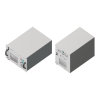
4.4 INSTRUCTIONS FOR CONNECTING STAINLESS STEEL TUBES
The hydrogen gas connections needed are tube fittings for ¼” (H
2
pipes) and ⅜” (O
2
pipe) outside
diameter (OD) tubes. The outlets to be connected according to these instructions are labelled “H
2
OUT”
and “H
2
VENT” as well as “O
2
VENT” on the front panel of the device.
Follow the below instructions carefully – please refer to the Swagelok manufacturers installation guide
for any further details: An Installer's Pocket Guide for Swagelok® Tube Fittings (MS-13-151).