activated, the button is semi-lit, shown by the symbol under it: . A second
press on the button switches back to the LP/HP filter (button unlit).
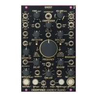
26. RESONANCE KNOB: manual control over the RESONANCE OF THE
FILTER ; is summed with the external CV applied to the RESONANCE CV
input jack (27). When the BAND-PASS filter is selected (25), this knob defines
the width of the band. In COMB FILTER mode this knob is bipolar and
defines the feedback adding negative (to CCW) and positive (CW) combs and
at maximum side CW/CCW values enables the resonator. Secondary hidden
function (holding ROUTING while turning RESONANCE ) lowers the SAMPLE
RATE
FW V3.0
amount output of the FILTER chain: full 96 kHz at CCW and
crushing to a certain moment until the audio falls down to noise. When
turning feature, it radically brings aliasing to the audio signal – use on your
own discretion creatively to add lo-fi flavor.
27. RESONANCE CV INPUT JACK: 0…+5V external CV control for
the RESONANCE of the filter (26).
28. /ENV DEPTH* LED: Brightness shows the internally generated
envelope from trigger input (29). When SIDECHAIN KNOB (30) turned while
pressing the ROUTING /* button, this LED shows the amount of the
envelope applied to the internal sidechain audio ducking effect.
29. TRIGGER INPUT JACK: trigger input for the onboard sidechain
envelope.
30. SIDECHAIN KNOB: Sets the decay of the onboard envelope from
zero (no envelope) to approx. 5 seconds. When turned while pressing the
ROUTING /* button, this knob adjusts the depth of the envelope to the
internal sidechain audio ducking effect.
31. ENVELOPE OUTPUT JACK: 0…+5V envelope output triggered
from TRIG IN jack (29). The envelope has fixed 1mSec attack and a
natural-sounding exponential curve. While the internal envelope for
sidechaining is negative (to duck the audio), this output provides a positive
version of the envelope to use elsewhere in your system or modulating
module’s parameters.
32. COMPRESSOR KNOB: manual control over the amount of
compression applied after the effects processing chain is summed with an
external CV applied to the COMPRESSOR CV IN jack (33).
33. COMPRESSOR CV IN JACK: 0…+5V external CV input for the
compressor amount (32).
34. VOLUME /drive KNOB: controls the final output volume. Acts as an
attenuator for the POST VCA CV jack (35). When the knob passes after 15
o’clock it adds extra DRIVE saturation to the output signal while trying to