🠚 STEREO: left and right inputs tap independently in their corresponding
left and right outputs. In this mode the total delay time is halved (three
blinks when enabled)
18. CLOCK IN JACK: 0…+5V external input for the clock that sets the
TEMPO of the delay. External clock expects the clock pulses in sixteenth
notes. Module switches to external clock automatically when a patch cable is
inserted in the CLOCK IN jack: TAP button (17) blinks semi-lit following that
incoming clock.
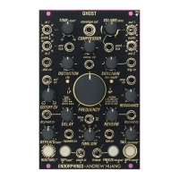
19. REVERB DRY/WET CV JACK: 0…+5V external CV control over
the DRY/WET MIX OF THE REVERB . Normalled to +5V when no patch cable
is inserted.
20. REVERB KNOB: manual control of the REVERB DRY/WET mix level,
acts as attenuator for DRY/WET CV jack (19). FW V2.0: secondary /TONE*
function (holding ROUTING while turning REVERB ) adjusts the tilt EQ before
the reverb tank (see advanced reverb parameters below).
21. TAIL /PREDELAY* KNOB: primary function controls the decay of the
REVERB’s TAIL . Secondary function in combination with ROUTING /* button
controls the AMOUNT OF PRE-DELAY for the reverb. Is summed with an
external CV applied to the TAIL CV input jack (22).
22. TAIL CV INPUT JACK: 0…+5V external CV input for the DECAY of
the reverb (21).
23. FREEZE /REVERSE* BUTTON: primary function freezes the reverb or
the delay, allowing you to hold a part of audio until you press this button
again. When freeze is enabled, this button is fully lit, shown by the symbol
under it: . Secondary function in combination with ROUTING /* button
switches the algorithm to REVERSE REVERB . When reversed reverb is
activated, the button is semi-lit, shown by the symbol under it:
When REVERSE REVERB activated, a single FREEZE button press along with
FREEZE trigger input activates and deactivates delay freeze – a.k.a. LOOPER
(infinitely recirculating delay’s audio buffer).
24. FREEZE JACK: 0…+5V external trigger input to enable the
FREEZE/LOOPER of the reverb or the delay (23) from incoming voltage
pulses. Has a latch action: each consequent trigger either enables or
disables that feature.
25. BPF /comb* BUTTON: switches the filter type from default
STATE-VARIABLE FILTER LP/HP to BAND-PASS filter and back. When
band-pass filter is enabled, this button is fully lit shown by the symbol under
it: . Secondary function switches to COMB FILTER with resonator by using
the ROUTING + BPF /COMB* button combo. When the COMB FILTER is