Cubemass DCI
8 Endress+Hauser
Electrical connection,
terminal assignment
Electrical values for inputs/outputs È Operating Instructions
Electrical connection,
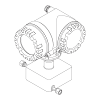
Remote version
A0003681
Connecting the remote version
a Transmitter wall-mount housing: non-hazardous area → separate documentation
b Transmitter wall-mount housing: ATEX II2G / Zone 1 / NEC/CEC → separate Ex documentation
c Sensor connection housing
d Cover of connection compartment or connection housing
e Connecting cable
Terminal No.: 4/5 = gray; 6/7 = green; 8 = yellow; 9/10 = pink; 11/12 = white; 41/42 = brown
Supply voltage 85 to 260 V AC, 45 to 65 Hz
20 to 55 V AC, 45 to 65 Hz
16 to 62 V DC
Cable entries Power supply and signal cables (inputs/outputs):
• Cable entry M20 × 1.5 (8 to 12 mm / 0.31 to 0.47")
• Threads for cable entries, ½" NPT, G ½"
Connecting cable for remote version:
• Cable entry M20 × 1.5 (8 to 12 mm / 0.31 to 0.47")
• Threads for cable entries, ½" NPT, G ½"
Terminal No. (inputs/outputs)
Order version 20 (+) / 21 (-) 22 (+) / 23 (-) 24 (+) / 25 (-) 26 (+) / 27 (–)
Fixed communication boards (permanent assignment)
8CN**–**S********* – –
Frequency output,
Ex i, passive
Current output, Ex i,
active, HART
8CN**–**T********* – –
Frequency output,
Ex i, passive
Current output, Ex i,
passive, HART
8CN**–**Q********* – – Status input MODBUS RS485
Flexible communication boards
8CN**–**D********* Status input Relay output Frequency output Current output, HART
8CN**–**M********* Status input Frequency output 2 Frequency output 1 Current output, HART
8CN**–**N********* Current output Frequency output Status input MODBUS RS485
8CN**–**1********* Relay output Frequency output 2 Frequency output 1 Current output, HART
8CN**–**2********* Relay output Current output 2 Frequency output Current output 1, HART
8CN**–**7********* Relay output 2 Relay output 1 Status input MODBUS RS485
4 5 6 7 8 9 10 11 12 41 42
4 5 6 7 8 9 10 11 12 41 42
S1 S1 S2 S2 GND TM TM TT TT
++ ++
++ ++
S1 S1 S2 S2 GND TM TM TT TT
a
b
c
d
d
d
e
 Loading...