Electrical connection Flowmeter Proline 200
18 Endress+Hauser
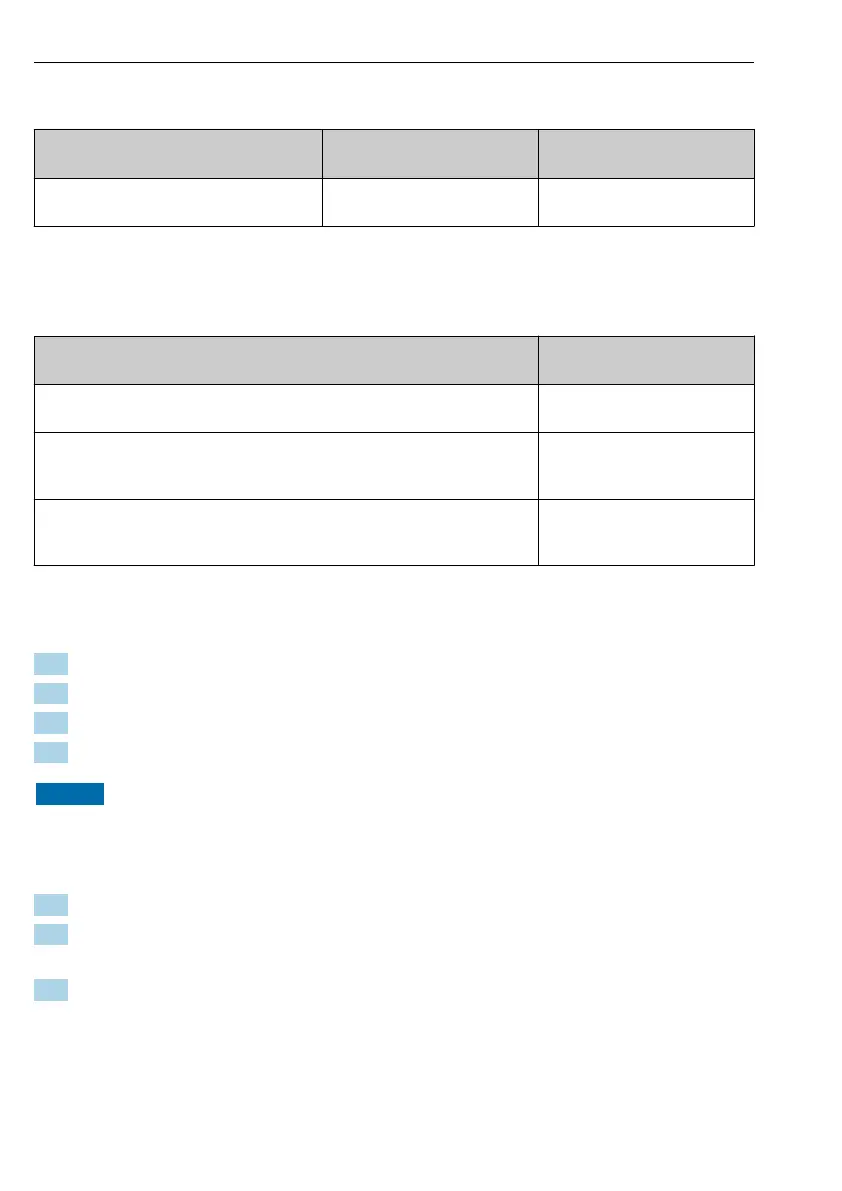
Supply voltage for a compact version without a local display
1)
Order code for "Output" Minimum
terminal voltage
2)
Maximum
terminal voltage
Option E: FOUNDATION Fieldbus, pulse/
frequency/switch output
≥ DC 9 V DC 32 V
1) In event of external supply voltage of the power conditioner
2) The minimum terminal voltage increases if local operation is used: see the following table
Increase in minimum terminal voltage
Local operation
Increase in minimum
terminal voltage
Order code for "Display; Operation", option C:
Local operation SD02
+ DC 1 V
Order code for "Display; Operation", option E:
Local operation SD03 with lighting
(backlighting not used)
+ DC 1 V
Order code for "Display; Operation", option E:
Local operation SD03 with lighting
(backlighting used)
+ DC 3 V
5.1.8 Preparing the measuring device
Carry out the steps in the following order:
1. Mount the sensor and transmitter.
2. Connection housing, sensor: Connect connecting cable.
3. Transmitter: Connect connecting cable.
4. Transmitter: Connect signal cable and cable for supply voltage.
NOTICE
Insufficient sealing of the housing!
Operational reliability of the measuring device could be compromised.
‣
Use suitable cable glands corresponding to the degree of protection.
1. Remove dummy plug if present.
2. If the measuring device is supplied without cable glands:
Provide suitable cable gland for corresponding connecting cable.
3. If the measuring device is supplied with cable glands:
Observe requirements for connecting cables → 13.