Do you have a question about the Endress+Hauser HMX50 and is the answer not in the manual?
Defines symbols used in the manual for safety warnings and procedures.
Identifies the intended users and required qualifications for operating the device.
Provides links and references to related documents and regulatory information.
Specifies the approved and appropriate applications for the HART Loop Converter.
Outlines scenarios where the device is not suitable or can lead to system failure.
Covers essential steps and precautions for installing the device correctly.
Details procedures for operating, maintaining, and repairing the device.
Provides guidelines for handling, transporting, and disposing of the device.
Describes the primary functions and capabilities of the HART Loop Converter.
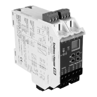
Details components on the front of the HMX50 device, including display and keypad.
Provides physical dimensions of the device with a drawing.
Specifies mounting on a 35 mm DIN mounting rail per EN 60715.
Instructions for snapping the device onto the DIN mounting rail and mounting terminal blocks.
Details how to connect the device, including input and output circuits.
Details how to connect the field circuit to the blue terminals, including torque specifications.
Instructions for connecting the drive circuit to the green terminals and terminal screw torque.
Explains connecting a HART handheld for diagnostics and data retrieval.
Details HART communication protocols like Burst Mode and Polling Mode.
Guides users through device configuration using front panel buttons and navigation.
Explains how to enter and navigate the device's parameterization menu for settings.
Details how to activate and use password protection to secure device parameters.
Step-by-step guide for entering the password to access parameterization mode.
Explains how to input numerical values for parameters via the device interface.
Provides format and examples for entering floating-point numbers in the device.
Allows selection of unit types (auto or custom) for HART variables displayed on the device.
Configures communication settings between the device and HART field devices, including mode and timeouts.
Configures the device to operate as a primary or secondary HART master.
Sets the time period for detecting HART communication loss.
Specifies the communication type between the isolated barrier and field device.
Assigns a short address for identifying field devices in a HART circuit.
Determines how the device identifies HART field devices in a circuit.
Assigns specific HART variables (PV, SV, TV, QV) to the current output.
Sets the characteristic curve for measuring underrange and overrange for current outputs.
Sets the lower limit for the current output signal range.
Sets the upper limit for the current output signal range.
Configures how the current output signals a fault condition to the controller.
Navigates through menu options for relay contact outputs.
Sets the threshold value for activating a relay contact output.
Assigns HART variables to be monitored by relay contact outputs.
Configures switching direction and operation mode for relay outputs.
Sets the specific threshold value for a relay output to trigger.
Sets the deadband around the trip point to prevent relay fluttering.
Prevents momentary trip value violations from being noticed.
Sets a delay for relay output response to prevent false alarms.
Accesses and displays fault messages related to relay outputs.
Allows selection of the display language for the device interface.
Enables password protection to prevent unauthorized parameter changes.
Restores the device to its original factory default configuration.
Shows the current software version installed on the device.
Explains the meaning of LEDs and display indicators during device operation.
Details fault messages sent by current outputs based on the selected characteristic.
Provides an overview of the device's default parameter settings.
References external technical information for additional device specifications.
| Manufacturer | Endress+Hauser |
|---|---|
| Output Signal | 4-20 mA, HART, PROFIBUS PA, Foundation Fieldbus |
| Process Pressure | Up to 40 bar |
| Housing Material | Stainless steel |
| Protection Class | IP67 |
| Display | Optional |
| Electrical Connection | Cable gland |
| Measured Variable | Flow |