DTT31, DTT35
10 Endress+Hauser
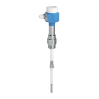
Mechanical construction
Design, dimensions DTT31,
DTT35
Dimensions
a0005279
All dimensions in mm (in)
L = insertion length (see ordering information, Pos. 080)
Connector M12x1 as per IEC 60947-5-2 (see ordering information, Pos. 020)
Valve connector M16x1.5 or NPT ½" as per DIN 43650A/ISO 4400 (see ordering information, Pos. 020)
DTT31 design, dimensions for
process connections
a0007101
Process connections DTT31 (see ordering information DTT31, Pos. 080)
Item No. Version DTT31 Insertion length L Thread length L
1
Screw-in length L
2
A Without process connection. For suitable welding bosses and compression
fittings see 'Accessories'.
30 and 100 mm
(1.18 and 3.94 in)
--
B Threaded process connection:
• ANSI NPT ¼" (m = AF14)
• ANSI NPT ½" (m = AF27)
• 14.3 mm (0.56 in)
• 19 mm (0.75 in)
• 5.8 mm (0.23 in)
• 8.1 mm (0.32 in)
C Cylindrical threaded process connection in inches as per ISO 228:
• G¼" (n = AF14)
• G½" (n = AF27)
• 12 mm (0.47 in)
• 14 mm (0.55 in)
-

 Loading...